
Simple Video Amplifier
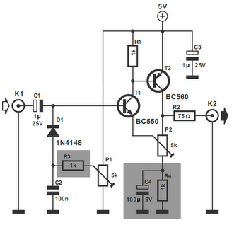
The video amplifier circuit is designed to enhance video signals while ensuring the integrity of the transistors involved. The circuit features two primary potentiometers, P1 and P2, which adjust the black level and signal amplitude, respectively. The potential risk arises when these potentiometers are set to their extremes, which can lead to excessive base currents flowing into the transistors T1 and T2.
To prevent transistor damage, resistors R3 and R4 are strategically placed in the circuit. These resistors act as current limiters, effectively capping the base currents to a safe level of no more than 5 mA. This precautionary measure is critical in maintaining the reliability and longevity of the transistors under varying operational conditions.
Additionally, the shunt capacitor C4 is included in the design to ensure that the resistor R4 does not adversely affect the overall amplification of the video signal. By providing a low-impedance path to ground for high-frequency signals, C4 helps maintain the desired frequency response and stability of the amplifier circuit.
Overall, the careful selection of components and their configuration in this video amplifier circuit not only enhances performance but also safeguards against potential damage, making it a robust solution for video amplification applications.The video amplifier in the diagram is a well-known design. Simple, yet very useful, were it not for the ease with which the transistors can be damaged if the potentiometers (black level and signal amplitude) are in their extreme position. Fortunately, this can be obviated by the addition of two resistors. If in the diagram R3 and R4 were direct co nnections, as in the original design, and P1 were fully clockwise and P2 fully anticlockwise, such a large base current would flow through T1 that this transistor would give up the ghost. Moreover, with the wiper of P2 at earth level, the base current of T2 would be dangerously high. Resistors R3 and R4 are sufficient protection against such mishaps, since they limit the base currents to a level of not more than 5 mA.
Shunt capacitor C4 prevents R4 having an adverse effect on the amplification. 🔗 External reference
Related Circuits
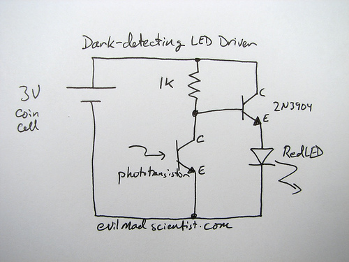
The following circuit illustrates a simple and inexpensive dark-detecting LED circuit. Features include the use of photoresistors, specifically a photocell or LDR, and an LED. This circuit utilizes a light-dependent resistor (LDR) as the primary sensing element. The LDR exhibits...
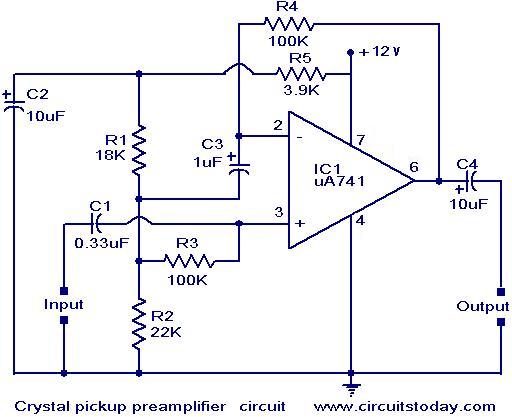
A preamplifier that operates on a single supply and is suitable for high-impedance crystal pickups is presented here. The circuit functions as a non-inverting AC amplifier, with the gain determined by the feedback resistor R4; a smaller R4 results...
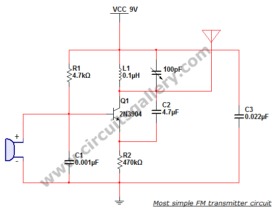
This is the simplest single transistor FM wireless transmitter circuit ever posted in CircuitsGallery. In the field of telecommunications, frequency modulation (FM) transmits information by altering the frequency of a carrier wave based on the message signal. FM utilizes...
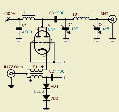
A powerful vacuum tube QRP amplifier designed for an 800mW QRPP homebrew telegraph vacuum tube transceiver named "3T." The decision to build this amplifier followed a period of using less than a watt of QRPP power for nearly a...
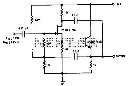
The 2N5485, which has a very low-capacity legacy, is always operated as a source follower with gate bias bootstrap. In this circuit, nothing is left to chance in reducing input capacitance. The 2N5485 is a JFET (Junction Field Effect Transistor)...
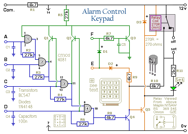
Pressing a single key on the keypad energizes the relay. Entering a four-digit code of your choice de-energizes the relay. The circuit was designed to control the Modular Burglar Alarm System but can have other applications. A five-digit version...
Warning: include(partials/cookie-banner.php): Failed to open stream: Permission denied in /var/www/html/nextgr/view-circuit.php on line 713
Warning: include(): Failed opening 'partials/cookie-banner.php' for inclusion (include_path='.:/usr/share/php') in /var/www/html/nextgr/view-circuit.php on line 713