
Simple-window-detector
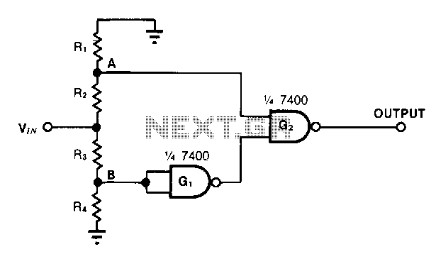
This simple window detector utilizes half of a 7400 quad NAND gate along with four resistors, selected to ensure that the voltage at point A exceeds the voltage at point B for any input voltage. When no input is applied or when VIN is at ground level, the output of gate G1 is high (logic one), which means that the output of gate G2 is also high. As the input voltage increases, VA rises more rapidly than VB. When VA reaches an acceptable threshold, the circuit's output drops to low (logic zero). As the input continues to increase, VB rises to an acceptable level, resulting in the output of G2 switching back to high.
The window detector circuit operates on the principle of comparing two voltage levels to determine the output state. The configuration employs one NAND gate (G1) to monitor the voltage at point A (VA) and another NAND gate (G2) to monitor the voltage at point B (VB). The resistors in the circuit are critical for setting the reference levels for VA and VB, allowing for precise control over the input voltage range that the circuit can handle.
Initially, with no input voltage applied, both gates output a high signal due to the NAND gate's characteristic behavior. As the input voltage (VIN) is applied and begins to rise, the voltage at point A increases more rapidly than that at point B, leading to a scenario where VA surpasses VB. This change triggers the output of G1 to drop to low, consequently affecting G2's output state.
The transition points in the circuit are defined by the values of the resistors, which can be adjusted to set the desired voltage thresholds for the window detector. This allows the circuit to be tailored for specific applications, such as over-voltage or under-voltage detection, where it is critical to monitor two different voltage levels and respond accordingly.
The design is compact and efficient, making it suitable for integration into various electronic systems requiring voltage monitoring and control. The use of a quad NAND gate allows for a reduction in component count, enhancing reliability and minimizing board space.This simple window detector uses only half of a 7400 quad NAND gate plus four resistors, chosen so that the voltage at point A exc.,eds the voltage at point B for any input voltage. With no input applied or when VIN is at ground, the output of gate Gl is one; hence G2"s output is also one.
As the input voltage increases, VA rises faster than JOB. When Va reaches an acceptable one level, the circuit"s output drops to zero. As the input continues to increase, JOB rises to an acceptable level, changing the output of G2 to one. 🔗 External reference