
Simplest Piezo Driver Circuit Explained
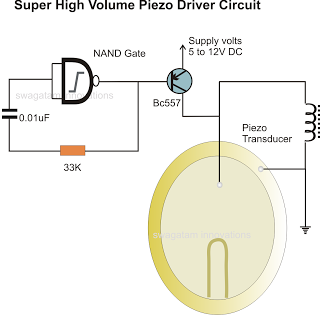
The circuit for driving a piezoelectric transducer typically involves several key components: a low-power signal source, a transistor, an inductor, and the piezo transducer itself. The signal source can be a microcontroller or any other low-frequency oscillator capable of generating a suitable signal. The transistor acts as a switch or an amplifier, allowing the low power signal to control a larger current flowing through the inductor.
The inductor plays a pivotal role in this circuit by storing energy when current flows through it. When the transistor is activated, the current builds up in the inductor, which then releases this energy to the piezo transducer, generating a mechanical vibration. This process effectively translates the electrical signal into a mechanical output, which is the fundamental operation of a piezoelectric device.
The choice of transistor is important, as it must be capable of handling the required current and voltage levels without overheating. Common transistor types used in this application include bipolar junction transistors (BJTs) or field-effect transistors (FETs), depending on the specific circuit requirements.
Additionally, the inductor value should be selected based on the frequency of operation and the desired resonance characteristics of the piezo transducer. A higher inductance will allow for more energy storage, enhancing the output to the transducer but may also affect the response time of the circuit.
In summary, the circuit for driving a piezoelectric transducer is a straightforward yet effective design that utilizes a transistor and an inductor to amplify a low-power signal, ultimately enabling the transducer to convert electrical energy into mechanical vibrations efficiently. Proper selection of components and circuit parameters is essential for optimal performance in various applications, including sound generation, sensing, and actuation.In the previous post we discussed a piezo transducer element and learned how to use it with electronic circuits. In this article we will see how a piezo tranducer can be driven or operated using a simple circuit. However the amplification procedure is not by using conventional amplifying circuits as used in systems incorporating speakers, but rath
er it is simply implemented through an inexpensive inductor. The low power frequency which may be available from a relevant circuit or an IC is first amplified using a transistor, and further more the transistor output is pumped up using an inductor. The use of a inductor becomes the most crucial stage for driving a piezo electric transducer. 🔗 External reference
Related Circuits

The charging apparatus depicted in the schematic circuit has a maximum output current of 20A and a maximum charging voltage of 80V. It can be adjusted starting from 0V, making it suitable for charging various types of batteries. The...
This is a variable power supply controlled by a PIC microcontroller. An LCD display is included in the circuit to show the actual output voltage and current values. A push-button switch is used to adjust the output voltage and...
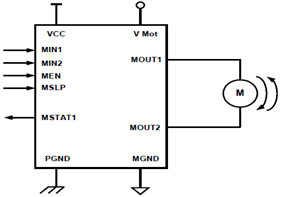
The schematic presented illustrates a 5A H-Bridge Module designed for the operation of a single Bipolar DC motor. The H-Bridge Module includes a header set (J2) and a connector terminal set (J1). Below is the pinout description for the...
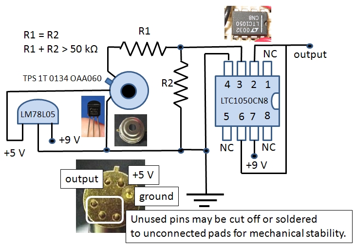
The Excelitas TPS 1T 0134 OAA060 thermopile sensor is a self-contained module that includes a built-in operational amplifier. The designation A2TPMI 334 OAA 60 is used in this document due to its previous identification under the PerkinElmer part number...

This transverter utilizes the bilateral properties of a balanced mixer to generate a 6-meter output from 2-meter inputs. The component Y1 is a 90-MHz crystal. It is important to note that the input frequency on the 2-meter band is...
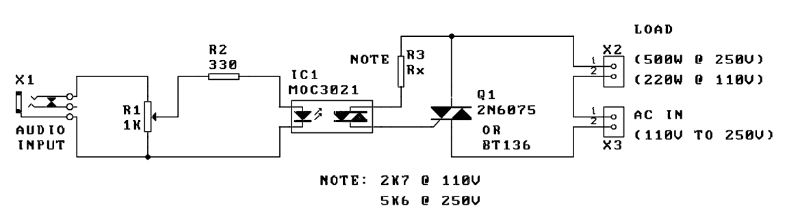
A music-to-light modulator is a circuit which controls the intensity of one or more lights in response to an audio input. The problem in older circuits is that there was a direct electrical connection between the lights using mains...