
Single-op-amp-clock
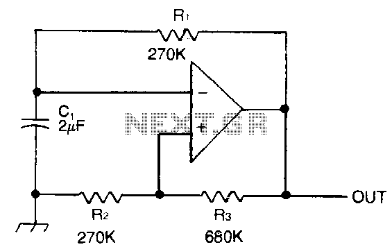
Capacitor C1 is charged through timing resistor R1 when the clock output is high. When C1 reaches the upper threshold voltage, the output signal decreases, and then C1 discharges through R1 until its voltage reaches the lower threshold point. When this happens, the output increases again and the cycle repeats itself. Using the parts values shown results in a frequency of 1 Hz. The output frequency can be adjusted by trimming the value of R1.
The described circuit operates as a simple astable multivibrator or timer circuit, utilizing a capacitor (C1) and a resistor (R1) to generate a square wave output signal. When the clock output is high, capacitor C1 begins to charge through the resistor R1. The charging process continues until the voltage across C1 reaches a predetermined upper threshold, at which point the output signal transitions to a low state. This transition indicates that the capacitor is fully charged.
Subsequently, C1 discharges through R1 until the voltage drops to a lower threshold level. Once this lower threshold is reached, the output signal switches back to a high state, initiating the cycle anew. The frequency of the output signal, which is defined as the rate of these cycles, is determined primarily by the values of C1 and R1. In this configuration, the circuit is designed to achieve a frequency of 1 Hz based on the specified component values.
Additionally, the output frequency can be fine-tuned by adjusting the resistance value of R1. This adjustment allows for greater flexibility in applications where specific timing intervals are required. The circuit can be implemented in various electronic applications, including timers, pulse generators, and frequency modulation systems, making it a versatile choice for engineers seeking to create timing solutions in their designs. Proper selection of component values is crucial for achieving the desired performance characteristics and ensuring reliability in operation.Capacitor C1 is charged through timing resistor R1 when the clock output is high. When C1 reaches the upper threshold voltage, the output signal decreases, and then C1 discharges through R1 until its voltage reaches the lower threshold point. When this happens, the output increases again and the cycle repeats itself. Using the parts values shown results in a frequency of 1 Hz. The output frequency can be adjusted by trimming the value of R1 🔗 External reference
Warning: include(partials/cookie-banner.php): Failed to open stream: Permission denied in /var/www/html/nextgr/view-circuit.php on line 713
Warning: include(): Failed opening 'partials/cookie-banner.php' for inclusion (include_path='.:/usr/share/php') in /var/www/html/nextgr/view-circuit.php on line 713