
Single op amp oscillator
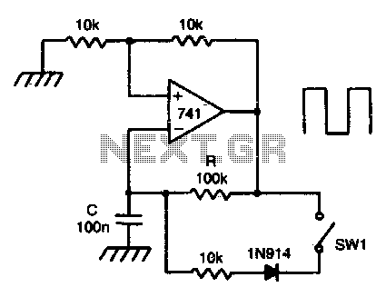
The circuit operates by utilizing the properties of the Schmitt trigger to introduce hysteresis into the voltage levels, which helps in creating a stable output signal even with noisy or slow input signals. The integrator function, provided by the op-amp, converts the input voltage into a ramp signal, which is then fed into the Schmitt trigger.
The RC network, consisting of a resistor and capacitor, determines the time constants for both charging and discharging phases. During the charging phase, the capacitor voltage rises exponentially until it reaches the upper threshold of the Schmitt trigger, causing the output to switch states. When the output transitions, the capacitor begins to discharge, and closing switch SWI shortens the discharge path, effectively reducing the time constant and allowing the capacitor to discharge rapidly.
The resulting square wave produced by the circuit has a duty cycle defined by the ratio of the time the output remains high (mark) to the time it remains low (space). With a 10:1 mark-to-space ratio, the output is high for a shorter duration compared to its low state, making this circuit suitable for applications requiring specific timing sequences or pulse generation. The design is compact and efficient, leveraging the characteristics of the op-amp to produce a reliable square wave output.This circuit has a Schmitt trigger and integrator built around one op amp. Timing is controlled by the RC network. Voltage at the inverting input follows the RC charging exponential within the upper and lower hysteresis levels. By closing the switch SWI, the discharge time of the capacitor becomes ten times as fast as the rise time
Thus a square wave with an 10:1 mark space ratio is generated. 🔗 External reference
Related Circuits
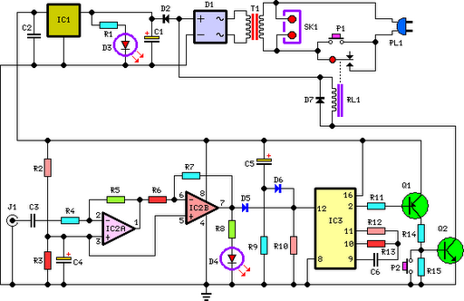
This circuit deactivates an amplifier or any connected device when a low-level audio signal at its input is absent for at least 15 minutes. Pressing P1 turns the device on, supplying power to any appliance connected to SK1. The...
The following circuit illustrates a Single Supply Phase Locked Loop Circuit Diagram. This circuit is based on the LM331 integrated circuit. Features include the response of... The Single Supply Phase Locked Loop (PLL) circuit utilizing the LM331 integrated circuit is...
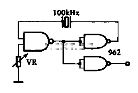
A DTL integrated circuit comprises a crystal oscillator, which is represented by the integrated circuits. The oscillation frequency ranges from 100 kHz to 1 MHz. Additionally, it includes a gate circuit that supplies a signal for the DTL oscillator...
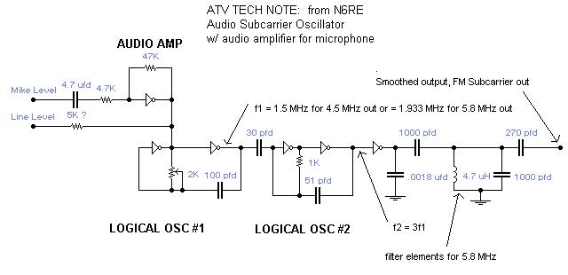
A single integrated circuit (IC) provides all amplifiers: the 74HC04 Hex Inverter, which is a digital component. The second oscillator synchronizes to three times the frequency of the first oscillator, thereby tripling the frequency modulation (FM) deviation. Utilizing the...
The schematic below illustrates the division of a crystal oscillator signal by the crystal frequency to obtain an accurate 1-second time base with a precision of 0.01%. Two cascaded 12-stage counters (CD4040) form a 24-stage binary counter, and the...
The circuit is a modified Colpitts oscillator, tuned with MV209 varactor diodes. The resonating inductor and the drain choke are selected by a rotary switch. 1N5711 Schottky diode, D, clamps the maximum positive voltage on the gate of oscillator...