
Single-Phase Inverters
The single-phase inverter is a crucial component in various applications, including renewable energy systems and motor drives. The inverter's operation hinges on the precise control of the firing angles of the SCRs, which allows for modulation of the output voltage and frequency. The phase-angle control circuit typically employs a microcontroller or a dedicated integrated circuit to manage the timing of the SCR firing.
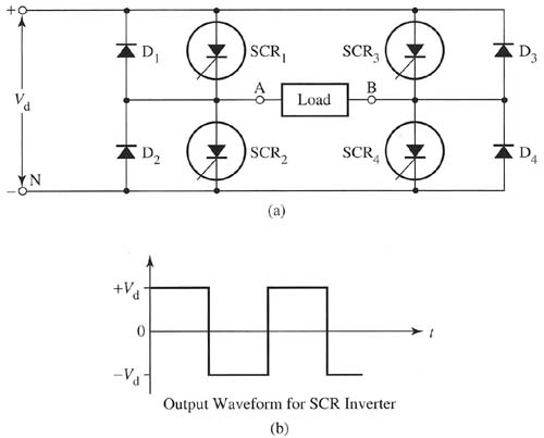
In the SCR-based inverter configuration, the four SCRs are arranged in a bridge topology, forming two pairs that correspond to the positive and negative halves of the AC waveform. When SCR1 and SCR4 are triggered, current flows through the load in one direction, producing the positive half-cycle. Conversely, triggering SCR2 and SCR3 allows current to flow in the opposite direction, generating the negative half-cycle. The result is an output waveform that approximates a square wave, which can be further processed using filters to produce a more sinusoidal output if required.
The load connected to the inverter may vary, ranging from resistive loads, such as incandescent lamps, to inductive loads, such as motors. The design of the inverter must take into account the load characteristics to ensure stable operation and to avoid issues such as voltage spikes or distortion in the output waveform.
In summary, the single-phase inverter using SCRs is a fundamental circuit for converting DC to AC, with applications in various electrical systems. Its operation relies on effective control of the SCR firing sequence, which is essential for generating the desired AC waveform and ensuring compatibility with the connected load.The simplest inverter to understand is the single-phase inverter, which takes a dc input voltage and converts it to single-phase ac voltage. The main components of the inverter can be either four silicon controlled rectifiers (SCRs) or four transistors.
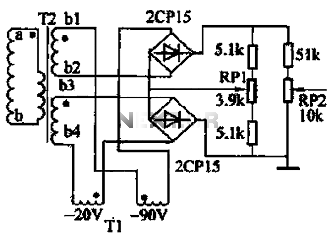
Fig. 1 shows a typical inverter circuit that uses four SCRs, and Fig. 2 shows a typical inverte r circuit that uses four transistors. Originally called a dc-link converter, now it`s simply called an inverter. Above: Fig. 1 (a) Electrical schematic of a typical inverter circuit that uses four silicon controlled rectifiers (SCRs). (b) Output waveform for SCR inverter. The diagram in Fig. 1 shows four SCRs used in the inverter circuit. In this circuit SCR1, and SCR4 are fired into conduction at the same time to provide the positive part of the ac waveform and SCR2 and SCR3 are fired into conduction at the same time to provide the negative part of the ac waveform.
The waveform for the ac output voltage is shown in this figure - notice that it`s an ac square wave. A phase-angle control circuit is used to determine the firing angle, which provides the timing for turning each SCR on so that they provide the ac square wave. The load is attached to the two terminals where the ac square wave voltage is supplied. 🔗 External reference
Related Circuits
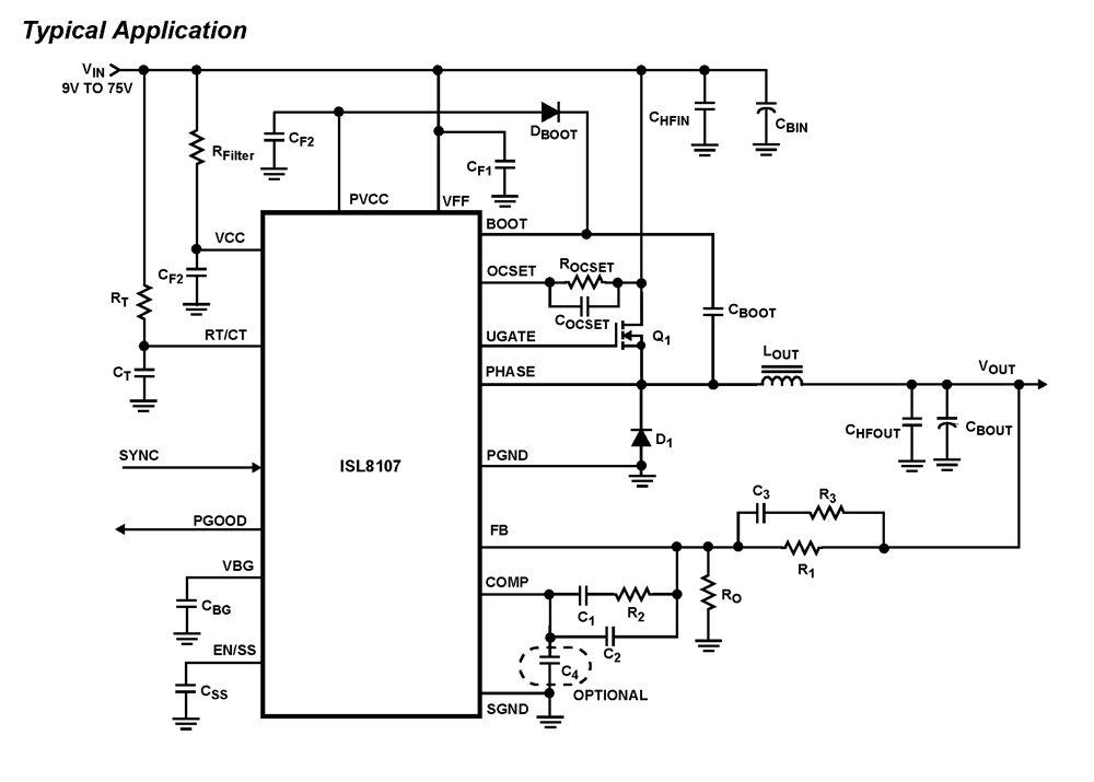
The ISL8107 is a single-phase, non-synchronous buck controller equipped with an integrated high-side MOSFET driver. It operates within an input voltage range of 9V to 75V. The internal reference voltage is 1.192V with a tolerance of ±1% across the...
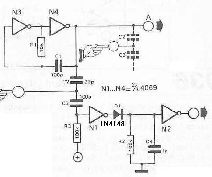
This touch sensor switch is designed using inverters (N1, N2) and several common electronic components. In the standby state, a signal is produced by the oscillator N3/N4 at the inputs of N1. When the touch sensor is activated, the...
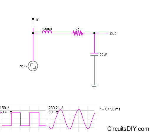
It is relatively easy to find square wave inverter circuits online. However, to operate most loads such as fans and televisions, a sine wave inverter is required. Constructing a sine wave or near-sine wave inverter is more complex and...
The closed-loop system consists of longitudinal and transverse components. The circuit operates as follows: a control circuit from the stepping motor CNC system issues a command, which the receiver detects. This signal is processed through a phase-sensitive rectifier to...
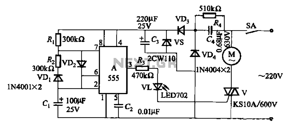
The circuit depicted in Figure 3-16 utilizes a 555 IC (Integrated Circuit) as the control element. It features a capacitive step-down circuit and incorporates a bidirectional thyristor (V) for intermittent motor control operation. By adjusting the resistance values of...

The versatile circuit can be employed to achieve various functions, including an astable multivibrator, a monostable multivibrator, a switch debouncer, or a frequency discriminator. Inverters U1a and U1b are configured as a latch. When the input voltage (VIN) is...