
Single source emergency lighting system
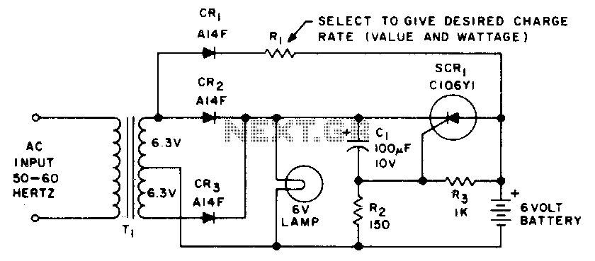
The emergency lighting system is designed to ensure reliable illumination during power outages or failures. It consists of a 6-volt rechargeable battery, which serves as the primary power source when the main AC supply is interrupted.
The system incorporates a battery management circuit that continuously monitors the battery's voltage level, ensuring it remains fully charged while connected to the AC supply. This is typically achieved through a dedicated charging circuit that utilizes a transformer to step down the AC voltage, followed by a rectifier to convert the AC to DC, which is then used to charge the battery.
In the event of a power failure, the system employs a switching mechanism, often utilizing a relay or a solid-state switch, to automatically disconnect the AC supply and connect the battery to the load, which consists of the emergency lighting fixtures. This transition must occur seamlessly to provide uninterrupted lighting.
To enhance the system's reliability, additional features may include overcharge protection, which prevents the battery from being charged beyond its capacity, and low-voltage disconnect, which ensures the battery does not discharge below a critical level, thereby prolonging its lifespan.
LED indicators may also be integrated into the design to provide visual feedback regarding the system's operational status, such as indicating when the system is operating on battery power or when the battery is charging.
Overall, the emergency lighting system is a vital component in ensuring safety and visibility during unexpected power outages, making it an essential feature in both residential and commercial applications.This emergency lighting system maintains a 6 volt battery at full charge and switches automatically from the ac supply to the battery. 🔗 External reference
Related Circuits
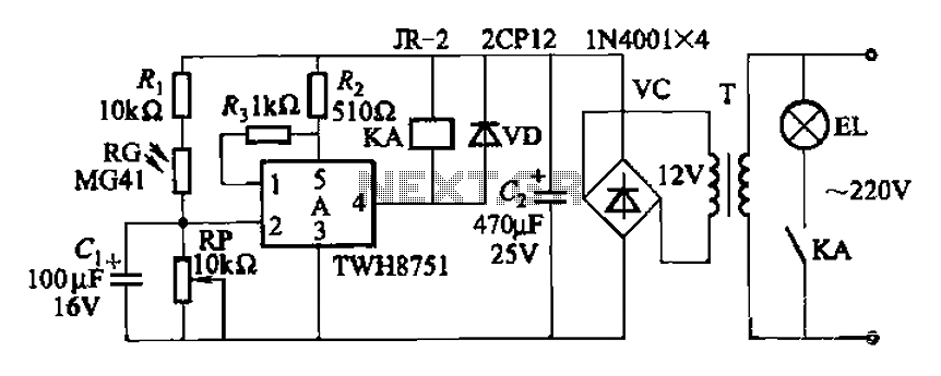
The adjustment potentiometer RP can modify the sensitivity of the device. Capacitors C1 function as an anti-light interference mechanism for instantaneous action. The adjustment potentiometer (RP) is a variable resistor that allows for fine-tuning of the device's sensitivity. By altering...

The hum noise is produced by an electronic device with improper design. To address this issue, it is essential to identify the source of the hum. This involves checking the grounding, cabling, casing, and other factors that may contribute...
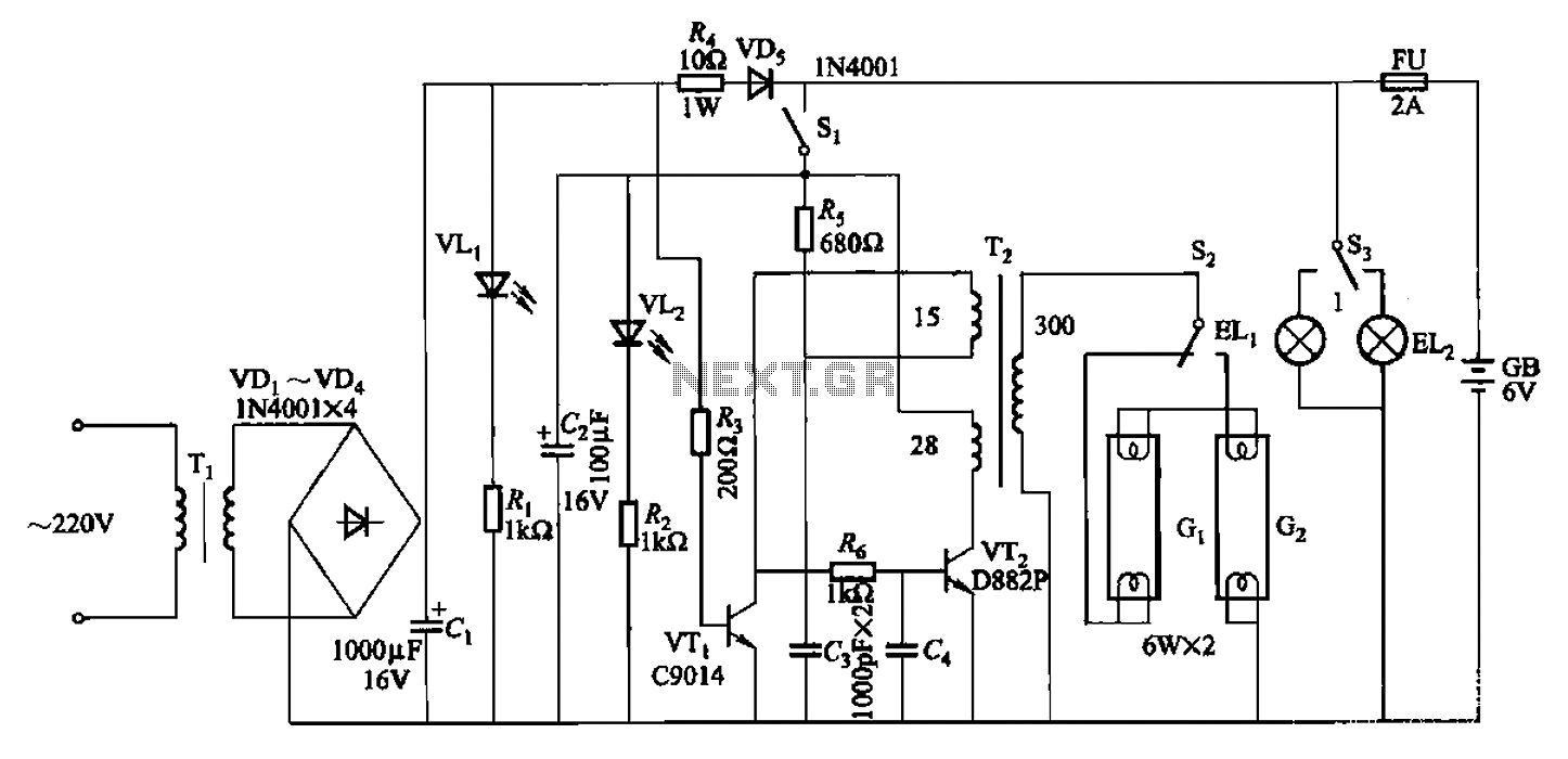
The 786A multi-functional double-tube fluorescent emergency circuit is illustrated in Figure 2-129. This circuit shares similarities with Figure 2-125. The 786A multi-functional double-tube fluorescent emergency circuit is designed to provide illumination during power outages or emergencies. It utilizes two fluorescent...
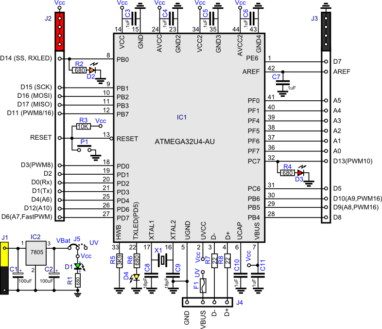
This project involves creating a clone of the Arduino Leonardo in a simplified manner. Consequently, the pin distribution does not conform to the standard Arduino layout. The Arduino Leonardo clone project focuses on replicating the functionality of the original Leonardo...
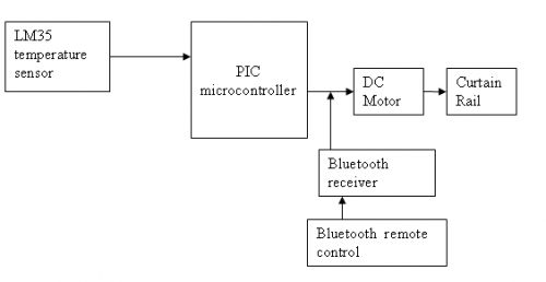
The circuit is designed for a DC motor and Bluetooth system, where the Bluetooth remote control is utilized to open and close curtains. A block diagram is provided for reference. A mobile phone can be used to develop a...
The current source in the diagram reacts very quickly to changes in the input signal and may be utilized in specific measurements. Differential. The current source depicted in the schematic is designed to provide a stable output current that responds...