
Single Span HF Test Oscillator
The internal construction of the oscillator is illustrated, showcasing the straightforward assembly method utilizing a section of folded tinplate from a tin can to form the box's walls. Manual tuning of a VCO across a broad spectrum often necessitates a multiturn precision variable wirewound resistor. However, due to the high cost of these components, alternative solutions are explored to reduce expenses while maintaining functionality.This compact RF oscillator covers the entire 0. 4 - 30 MHz range in a single sweep of the dial and has a terminated 50 ohm output of more than 300mV across the entire HF band. Most signal generators use a series of ranges to cover the HF band. This oscillator is a little different. It tunes the entire HF band from 400 kHz to above 30 MHz in a singl e range. It was designed to test receiver front end designs and HF filters and be compact enough to sit around my workshop bench. The oscillator output level also allows it to be used as a temporary oscillator for testing diode mixers, and it`s sine wave output minimizes harmonics.
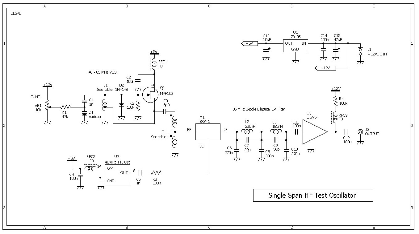
It`s not possible to directly cover the entire HF band in one range with a traditional LC oscillator. However, mixing an oscillator operating on a higher frequency band with a lower frequency fixed oscillator, it is possible to achieve the required range.
This is shown in the design`s schematic in Figure 1. A voltage controlled oscillator (VCO) operates from 48 MHz to 85 MHz. The VCO output (100-150mVpp into 50 ohms) is mixed with the output of a 48 MHz crystal oscillator in a diode mixer to give the required output. The varicap diode is the key to successful wide range VCOs, and the device I used was one of four recovered from an old video recorder tuner.
Other wide range varicaps such as Motorola`s MV104 or a Philips BB911 will also work well. The 48 MHz crystal oscillator is typical of those found in equipment such as printers, video cards and the like. These provide a 5V square-wave TTL- compatible output level. I found two plastic encapsulated 48 MHz oscillators in an old Epson printer. The output of the crystal oscillator I used was unable to drive the diode mixer directly, but the series combination of C5 and R3, a 1000pF ceramic capacitor and a 100 ohm resistor, worked well.
The square wave output is also ideal for diode mixers. The use of a 48MHz oscillator, and the resulting VCO range, was largely based on the availability of suitable parts. If you are looking to substitute parts and to modify the design to suit, the VCO frequency must be high enough to permit the required 30 MHz range to be achieved within a single span.
It`s unlikely that any lower VCO frequency range would be successful. Also, the crystal oscillator, which sets the lower VCO frequency bound, must be far enough away from the upper output frequency of 30MHz to allow the simple 3-pole low pass filter stage to filter off any residual 48MHz oscillator signal as well as the sum component of the mixer output. The prototype reached 35 MHz with an output rolloff of about 3dB. The output of the SRA-1 double balanced mixer (DBM), M1, provides both difference (wanted) and sum (unwanted) products.
A variety of diode-type DBMs will work fine here, including one made from 1N4148 diodes and a couple of ferrite beads. The desired (difference) output is selected using a 3-pole elliptical filter. This filter also places a notch at 48MHz to minimize any oscillator feed-through. The filtered output is then amplified by 20dB with an ERA-5 Mini-Circuits MMIC amplifier to give an output of 300 400 mVpp into a 50 ohm termination.
I used a surface mount version of the ERA-5 amplifier which is around half the size of a grain of rice. Careful soldering is required. When operating, the unit draws just over 100mA at 12V. Not really suited to battery use, but then this oscillator is really intended for the test bench. A well-regulated supply is required since this voltage directly feeds the varicap. Photo 2: The view inside the box illustrates the simple construction method used with a section of folded tinplate from a tin can used to form the walls of the box.
Manual tuning of a VCO across a broad range of spectrum like this often requires a multiturn precision variable wirewound resistor. With these now costing as much as $US20, I looked for a cheaper alternative. The solution lay in using 🔗 External reference
Related Circuits
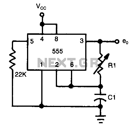
The frequency of oscillation depends on the Rl/Cl time constant, allowing for frequency adjustment by varying Rl. This is a basic circuit. The described circuit operates based on the relationship between resistance (Rl) and capacitance (Cl), which together form a...
The CAMD CM8870 CM8870C offers complete DTMF receiver functionality by combining both the band-split filter and digital decoder capabilities into a single 18-pin DIP, SOIC, or 20-pin PLCC package. The CM8870C is produced using advanced CMOS process technology, ensuring...
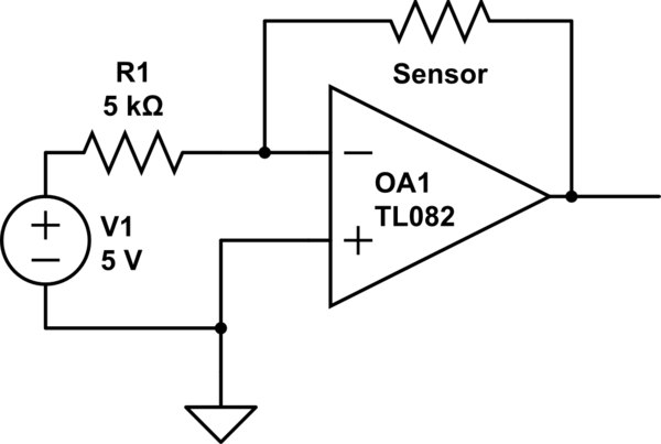
The installation involves a solid-state OEM water depth sensor designed for continuous fluid level measurement. This sensor outputs a resistive signal that is inversely proportional to the liquid level: as the liquid level decreases, the output resistance increases, and...
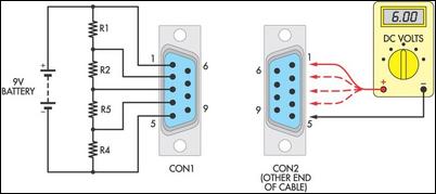
Many cable testers have been previously published, some of which are quite complex. However, here is a cost-effective and straightforward alternative. It utilizes only a 9V battery, two mating connectors, and several resistors, along with a multimeter for voltage...
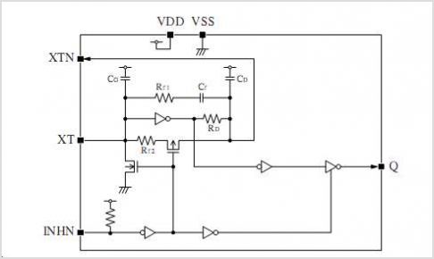
The figure illustrates the FM modulation circuit of a crystal oscillator. FM modulation can be achieved through direct and indirect methods. The direct FM method involves directly altering the frequency of the oscillating circuit. While this approach is straightforward,...
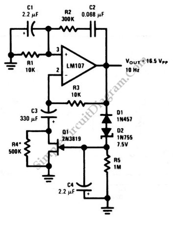
This is a Wien-bridge sine-wave oscillator circuit. This circuit utilizes negative-feedback stabilization to ensure that the gain does not exceed unity. The Wien-bridge oscillator is a type of electronic oscillator that generates sine waves. It consists of an amplifier and...