
Single-supply-fault-monitor
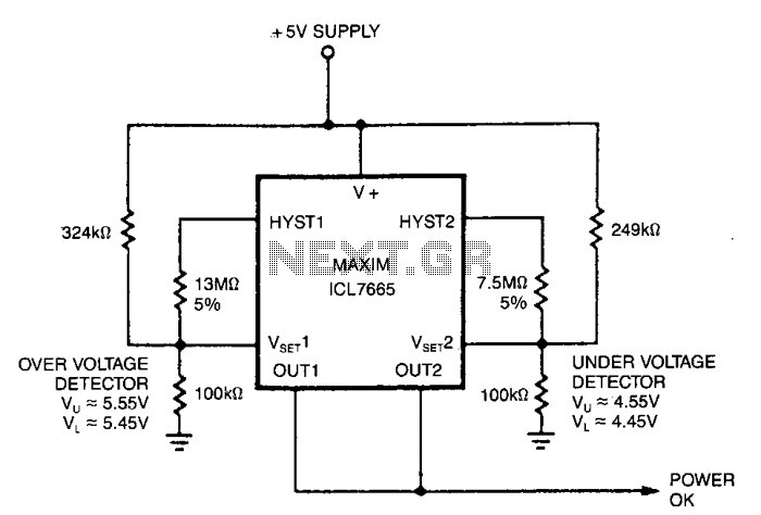
This circuit illustrates a standard over/under-voltage fault monitor designed for a single power supply. The upper trip points, which control OUT 1, are set at 5.5 V with a hysteresis of 100 mV (Wu = 5.55 V, L = 5.45 V). The lower trip points, which control OUT 2, are centered at 4.5 V, also with a hysteresis of 100 mV. OUT 1 and OUT 2 are interconnected in a wired OR configuration to produce a power OK signal.
The over/under-voltage fault monitor circuit is essential for ensuring that the voltage levels remain within specified limits to protect sensitive electronic components. The upper trip point for OUT 1 is configured to activate when the supply voltage exceeds 5.55 V, while it deactivates when the voltage falls below 5.45 V. This hysteresis prevents rapid toggling of the output due to minor voltage fluctuations, which is crucial for stable operation.
Similarly, the lower trip point for OUT 2 activates when the supply voltage drops below 4.5 V and deactivates when the voltage rises above this threshold, also incorporating a hysteresis of 100 mV. The wired OR configuration of OUT 1 and OUT 2 allows for a single power OK signal to be generated. This signal indicates that the supply voltage is within the acceptable range, providing a simple yet effective means of monitoring the power supply status.
In practical applications, this circuit can be implemented using operational amplifiers or comparators configured to sense the voltage levels. The output signals can be used to trigger alarms, enable or disable power to other circuits, or provide feedback for microcontroller inputs. This design is particularly advantageous in power management systems, battery-operated devices, and various electronic applications where voltage regulation is critical.This circuit shows a typical over/under-voltage fault monitor for a single supply. The upper trip points, controlling OUT 1, are centered on 5.5 V with 100 mY of hysteresis Wu = 5.55 V, "L = 5.45 V); and the lower trip points, controlling OUT 2, are centered on 4.5 V, also with 100 mV of hysteresis. OUT 1 and OUT 2 are connected together in a wired OR configuration to generate a power OK signal. 🔗 External reference