
Siren circuit
The circuit described is designed to generate an altered sound resembling that of a siren. It utilizes an oscillator formed by two NAND gates (IC1a and IC1b), which operate at a very low frequency. This low-frequency oscillation is critical as it drives an electronic switch (IC2), which can open and close in sync with the oscillation frequency.
When the switch IC2 is closed, the supply voltage charges capacitor C3 through resistor R2. The charging of C3 is essential as it stores energy that will be released when the switch opens. When IC2 opens, capacitor C3 discharges through resistor R3. The voltage across C3, which varies with the charge and discharge cycle, is used to control the Voltage Controlled Oscillator (VCO) within the Phase-Locked Loop (PLL) IC3. The output from the VCO produces the altered sound characteristic of a siren.
The circuit allows for experimentation with the values of the resistors and capacitors to modify the sound produced. Specifically, resistor R1 and capacitor C1 are used to control the timing of the operation, influencing how long the circuit remains in each state of oscillation. Resistor R4 and capacitor C2 are responsible for determining the frequency of the sound produced, while resistor R3 and capacitor C3 affect the characteristics of the sound change. By adjusting these components, various siren-like sounds can be achieved, making the circuit versatile for different applications.With this circuit we can create a altered sound of siren. The oscillator IC1a-b is constituted by two gates NAND, oscillating in very low frequency. This oscillation drive the IC2, that is a electronic switch, which opens and closes in the rythm of oscillation. When closes the switch then the voltage of supply charge the capacitor C3 through the resistance R2. When switch IC2 opens, the C3 discharge through the R3. The voltage with which is charge the C3, regulates the VCO of IC3, that is PLL, so that we have in the exit his one altered sound.
You can experiment with the prices of resistances and capacitors in order to you change the sound of siren. The R1, C1 check the time of operation, the R4, C2 check the frequency of produced sound and the R3, C3 check the change of sound.
🔗 External reference
Related Circuits
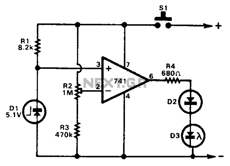
The 741 operational amplifier can function as a voltage comparator. It features a non-inverting input and a Zener-controlled voltage source, with a reference voltage set at 5.1V. Resistor R2 is used to adjust the in-phase input voltage to half...
Almost all 24V power systems in trucks, 4WDs, RVs, boats, etc., utilize two series-connected 12V lead-acid batteries. The charging system can only sustain the total voltage of the individual batteries. If one battery is failing, this circuit will illuminate...
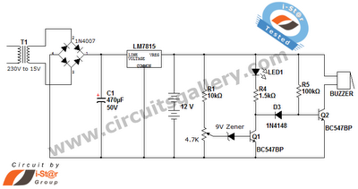
This is a straightforward 12V rechargeable smart battery charger circuit. It can be utilized as a charger for car batteries, inverter batteries, emergency light batteries, and more. An automatic indicator alarm circuit accompanies this battery charger schematic. The primary...
Nowadays electronic voting machines are being used effectively. The confidence of the voter in its flawless working is gradually building up and these machines are thus becoming quite popular throughout the country. Features of the electronic voting machine include...
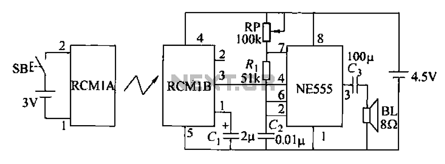
The circuit utilizes an RMIB multivibrator component that operates at a maximum distance. When the distance exceeds a specific threshold, the output pin of the receiver goes low, effectively stopping the oscillation. The NE555 multivibrator, which is part of...
This UHF transmitter is designed for low power applications such as remote controls for garage doors, operating systems, and wireless alarms. This UHF FM transmitter is equipped with... This UHF transmitter operates within the Ultra High Frequency (UHF) band, which...