
Slave Flash Trigger

The operation of the circuit begins with the response of phototransistor D5 to the external camera flash, which is pulsed by a transistorized amplifier T1 into the dual flip-flop clock IC1. One output of a flip-flop illuminates an LED as a "ready" signal. A double pole, 3-position slide switch, S1, allows the selection of no delay (e.g., for Kodak cameras) or one flash delay (e.g., for Olympus cameras) before triggering. Both flip-flops are utilized in the 4013 IC, with the clock signal derived from the flash being used to trigger the circuit on the rising clock signal, effectively dividing the signal by two and triggering the TIC206 triac on the first or second flash. A simple RC timed reset mechanism, consisting of R6 and C4, is incorporated to provide a relatively long delay (approximately half a second) before resetting the entire circuit. The advantage of using a triac is its ability to handle trigger voltages of either polarity. The 2N3906 transistor may be replaced by its near equivalent, the BC212L. The SFH300-2 photodiode is available from Maplin as part number MES NP64U, and the triac may also be a TIC126D.
This circuit is particularly useful for photographers who wish to enhance their images in low-light conditions by utilizing external flash units. The design allows for flexibility in flash timing, accommodating different camera models and their unique firing sequences. The inclusion of a phototransistor for optical triggering ensures a reliable response to the camera's flash, making it a valuable tool for both amateur and professional photographers. The circuit's simplicity and effectiveness in synchronizing additional flash units can significantly improve the quality of photographs taken in challenging lighting environments.Using any camera in a dull or dark environment generally requires the use of supplementary light. This is a standard technique, and even where adequate natural lighting exists, to take conventional film pictures with enhanced contrast using a fill-in` flash for foreground subjects in shade. A flash is often built into the camera body, but the inte rnal flash is not usually powerful enough to illuminate subjects much more that 3 m or so from the camera. On SLR cameras a hot-shoe is provided for triggering an auxiliary, more powerful flash, but the small pocket cameras are not so equipped.
However, it is possible to trigger a slave flash from the camera flash by optical means. Even so, things are not so simple, for some cameras, e. g. Olympus, Nikon, Canon actually fire twice, although it appears to be once to the naked eye. The first flash sets the exposure and the second takes the picture. Help on synchronisation requirements may be found at various websites maintained by professional photographers. See also for a series of articles with kits by a caving enthusiast. The presented trigger circuit optically receive the camera flashes and either fires at the same time as the first flash or has one flash delay before triggering the slave flash.
Additional counting circuitry is required for more than one delay (covered by modified circuit not presented here). Here`s how it works. The response of phototransistor D5 to the external camera flash is pulsed by a transistorised amplifier T1 into the dual flip-flop clock IC1.
One output of a flip-flop illuminates an LED as a ready` signal. A double pole 3-position slide switch, S1, selects none (e. g. for Kodak camera) or one (e. g. for Olympus camera) flash delay before triggering. Both flip-flops are used in the 4013, the clock signal derived from the flash is used (triggered on the rising clock signal) to divide by two` and trigger the TIC206 triac on the first or second flash. A simple RC timed reset mechanism around R6-C4 is used with a relatively long delay (about half a second) before resetting the entire circuit.
The advantage of the triac is that a trigger voltage of either polarity can be handled. The 2N3906 may be replaced by its near equivalent the BC212L. The SFH300-2 photodiode is supplied by Maplin as part number MES NP64U. The triac may also be a TIC126D. 🔗 External reference
Related Circuits

A Schmitt trigger provides effective squaring of the output, sometimes eliminating the need for an additional output stage. A Schmitt trigger is a type of comparator circuit that incorporates hysteresis, which allows it to provide clean, stable output transitions. This...

VDI, VD2, C3, and C4 form a simple half-wave rectifier capacitor step-down regulator circuit. This circuit can output approximately 12V DC voltage after power is applied across C3, which is utilized for the time base circuit. Additionally, the time...

The concept of this cost-effective flashing LED indicator is straightforward: it utilizes a low-frequency oscillator to control two LEDs. This flashing LED indicator circuit is designed to provide a visual signal using two light-emitting diodes (LEDs) that alternate in illumination....
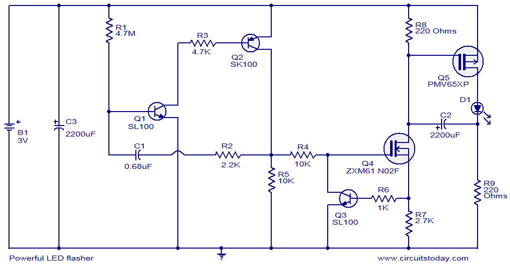
This circuit diagram illustrates a powerful LED flasher utilizing a 1W high power LED, which is widely available in the market. Transistors Q1 and Q2 are configured as an oscillator that generates positive pulses with a duration of 20...
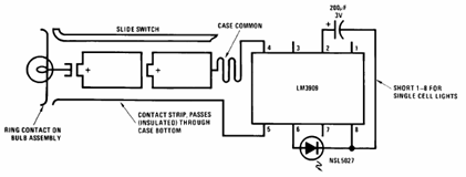
The schematic presented below illustrates the Flashlight Finder circuit diagram utilizing the LM3909, a monolithic oscillator specifically designed for flashing Light Emitting Diodes (LEDs). The Flashlight Finder circuit employs the LM3909 integrated circuit, which is capable of generating a series...
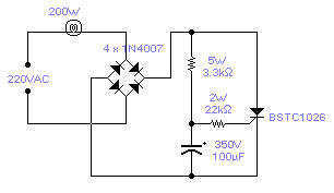
There is no need to resort to complex circuitry if what you are looking for is a simple power flasher. The light will flash at around 1Hz with a 100W bulb at a duty cycle of 50%. The max....