
Small Radio Transmitters
The small radio transmitter circuit is designed for efficient short-range audio transmission, making it ideal for applications like wireless microphones. The PCB dimensions of 1.75" x 2.5" facilitate compact integration into various enclosures or devices. The circuit operates within a frequency range that, while documented as 100-108 MHz, has been found to function effectively between 85-100 MHz, which may provide additional flexibility depending on local transmission regulations and receiver compatibility.
The input stage of the circuit, with a high impedance of 1 MΩ, allows for the connection of various audio sources without significant loading effects, ensuring high fidelity of the transmitted audio signal. The input sensitivity of 5 mV and the maximum input signal of 10 mV indicate that the circuit can handle standard microphone outputs and line-level signals, making it versatile for different audio applications.
The transmitter's mono output is suitable for basic audio transmission needs, and the ability to receive the signal on standard FM radios enhances its practicality for users. The kit form of the transmitter not only provides a learning opportunity for individuals interested in electronics but also allows for customization and experimentation with the design.
The PCB layout provided in PCBPLAN.GIF is critical for ensuring correct component placement and soldering, while TRACKS.GIF serves as a useful reference for replicating the track layout. Attention to detail in the construction process, especially regarding the printed coil, is essential for maintaining the integrity of the transmitter's performance. Overall, this small radio transmitter represents an accessible project for hobbyists and engineers alike, offering a balance of simplicity and functionality.Information about building a small radio transmitter, which has a PCB 1. 75" x 2. 5" (45mm x 68 mm) and has a range of about 30 yards or so. The documentation with the circuit says the freq range is 100-108 MHz, but I have found it to be more like 85-100 MHz. The circuit is (of course) only mono, and accepts an audio input from either a mic rophone or other source. The input impedance is 1Mohm. The input sensitivity is 5mV and the max input signal is 10mV. The transmitted signal can be picked up on a FM radio. The circuit can be used for short-range transmission, eg. for wireless microphones. The actual circuit comes from a `Kit`, available from Veleman electronics (USA distributor is Tapto Corp. , PO Box 1339, CLAREMONT NH-03743-US. UK distributor is High-Q Electronics, 382 Edgware Road, London, W2 1EB). The kit number is K1771. It is a very good transmitter. I bought the kit, and made the circuit, which worked very well. I wanted two transmitters, so I made my own `copy` PCB and built the circuit, and in fact my home-made version seems to work better than the original!
So there is no need to buy the kit really, as it is quite a simple circuit, and is the best `home-made` transmitter I have seen. PCBPLAN. GIF shows the PCB layout from above (components shown). PCBPLAN. GIF is an accurate layout, scanned from the instruction sheet. I have used * to mark one corner for reference. TRACKS. GIF shows the track layout on the soldering side of the board. This is NOT a very accurate layout. This is because I didn`t actually have a plan of the track layout. To get TRACKS. GIF, I put a bit of OHP film onto the bottom of the PCB, and traced the tracks with an OHP pen. I then scanned this in. I have marked the component leg holes (approximately) with white blobs. Then make your PCB. As mentioned earlier, PCBPLAN. GIF gives the accurate positioning of the holes, whereas TRACKS. GIF gives the positions only approximately. So use PCBPLAN when drilling the holes in your PCB board. Then draw on the tracks, using TRACKS. GIF as a guide. The important thing is to make sure you draw the `printed coil` correctly on the PCB - those lines are there for a reason!
🔗 External reference
Related Circuits
Crystal radios do not require external power sources to operate; they rely solely on radio waves. The first crystal set constructed was a "variometer" radio, which features a larger coil that slides over a smaller coil to modify the...
Connect the two sections of the variable capacitor (C3) in series to linearize the tuning somewhat. Use the connections on either end of C3 and do not use the middle lead. The gain is sufficient to drive an earphone....
Radio Control Circuits PDF Manual Download. This document serves as a comprehensive guide to radio control circuits, intended for individuals seeking to understand the principles and applications of radio frequency (RF) technology in controlling various devices. The manual covers fundamental...
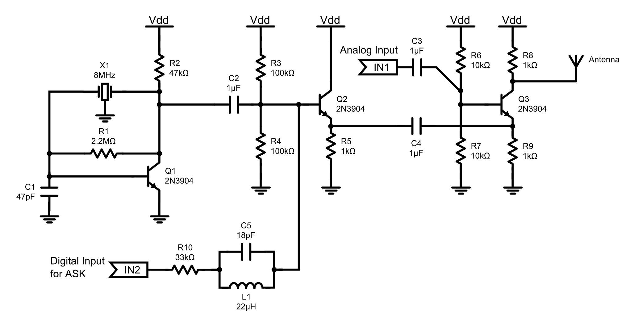
This is an 8MHz amplitude modulated (AM) radio transmitter designed primarily for practical applications and as an educational exercise in electronics. The objective was to create a simple radio transceiver that could be used in future projects requiring basic...
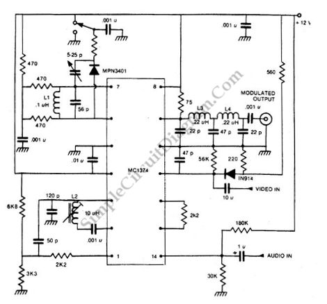
How can a television modulator be small and simple? First, it utilizes integrated circuits, and second, a TV modulator is essentially an amplitude modulator. Television modulators are essential components in the transmission of television signals, converting audio and video signals...
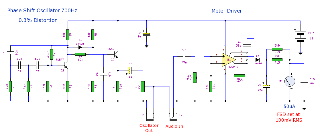
This is a compact general-purpose audio test set. It includes a low distortion (0.3%) phase shift oscillator and a level meter. The level meter is calibrated at 100mV full scale deflection (FSD) and is suitable for gain measurements and...
Warning: include(partials/cookie-banner.php): Failed to open stream: Permission denied in /var/www/html/nextgr/view-circuit.php on line 713
Warning: include(): Failed opening 'partials/cookie-banner.php' for inclusion (include_path='.:/usr/share/php') in /var/www/html/nextgr/view-circuit.php on line 713