
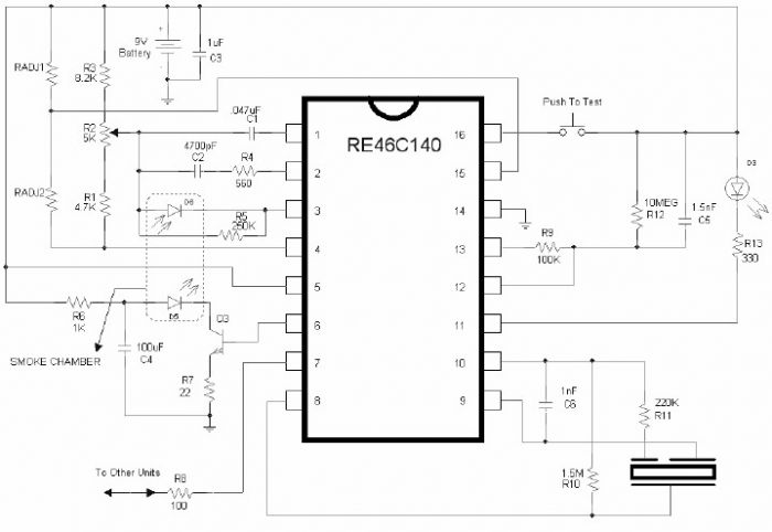
Smoke detector alarm schematic with RE46C140
The RE46C140 smoke detector circuit is designed to operate efficiently while ensuring reliable smoke detection. The core functionality relies on the low-power CMOS technology, which allows the device to maintain low standby currents, thus prolonging battery life in portable applications. The internal oscillator's design is crucial, as it balances the need for periodic power delivery to the smoke detection circuitry with energy conservation.
The LED serves multiple purposes, providing visual feedback during normal operation and alarm conditions. Its pulsing behavior is strategically implemented to convey the status of the device, enhancing user awareness. During standby, the infrequent pulsing minimizes power consumption while still allowing the user to confirm operational status. The increased frequency of the LED during alarm conditions ensures that the user is alerted promptly.
The comparator within the circuit plays a vital role in ensuring accurate smoke detection. By continuously comparing the output from the photo amplifier with a fixed reference voltage, the circuit can identify when smoke levels exceed predefined thresholds. This feature is critical for preventing false alarms while ensuring that genuine smoke conditions trigger the alarm.
The bidirectional I/O pin enhances the flexibility of the smoke detector system, allowing for the integration of multiple units. This feature is particularly useful in larger installations where multiple detectors may be required to ensure comprehensive coverage. The design ensures that the I/O pin can handle interconnections without risking damage to the circuit, even when shorted to ground.
Overall, the RE46C140 circuit is a well-rounded solution for smoke detection applications, combining efficiency, reliability, and user-friendly features into a compact design. The integration of these components and functionalities makes it suitable for both residential and commercial use, adhering to safety standards while providing essential smoke detection capabilities.Using the RE46C140 circuit can be designed a very simple smoke detector alarm using few external electronic components. The RE46C140 IC is a low power CMOS photoelectric type smoke detector IC that will provide all the required features for a photoelectric type smoke detector project.
An internal oscillator strobes power to the smoke detection c ircuitry for 100us every 10 seconds to keep standby current to a minimum. If smoke is sensed the detection rate is increased to verify an alarm condition. In standby the LED is pulsed on for 10mS every 43 seconds. In a local alarm condition or the push to test alarm the LED pulse frequency is increased to once every 5 seconds. In the case of a remote alarm the LED not active. In the timer mode of operation the LED is pulsed on for 10mS every 10 seconds. A comparator compares the photo amp output to an internal reference voltage. If the required number of consecutive smoke conditions is met the device will go into local alarm and the horn will be active.
The bidirectional IO pin allows interconnection of multiple detectors. In a local alarm condition this pin is driven high immediately through a constant current source. Shorting this output to ground will not cause excessive current. The IO is ignored as an input during a local alarm. 🔗 External reference
Related Circuits
This document serves as a supplementary guide to numerous existing resources that detail the construction of a USB charger. It is assumed that the reader possesses a basic understanding of electronics. The construction of a USB charger typically involves a...

The circuit utilizes the HL-169B voice alarm integrated circuit (IC). It is designed for use in security applications, including glass doors, car doors, and windows, to act as a burglar alarm. When a thief applies force to these items,...
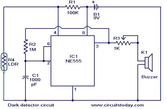
The dark detector circuit illustrated here is designed to generate an audible alarm when the ambient light in a room is turned OFF. The circuit is constructed around the timer IC NE555. A general-purpose light-dependent resistor (LDR) is utilized...
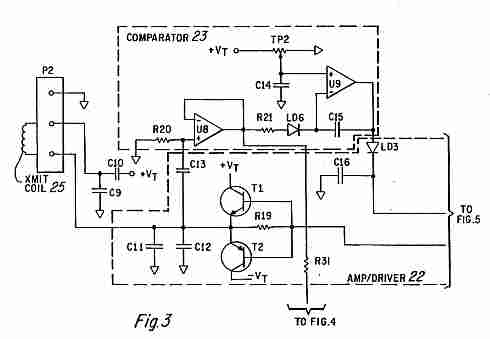
Coin detector and counter: How to detect different types of coins from their effect on an oscillating magnetic field. A coin detector and counter operates by utilizing the principles of electromagnetic induction to identify and differentiate between various types of...
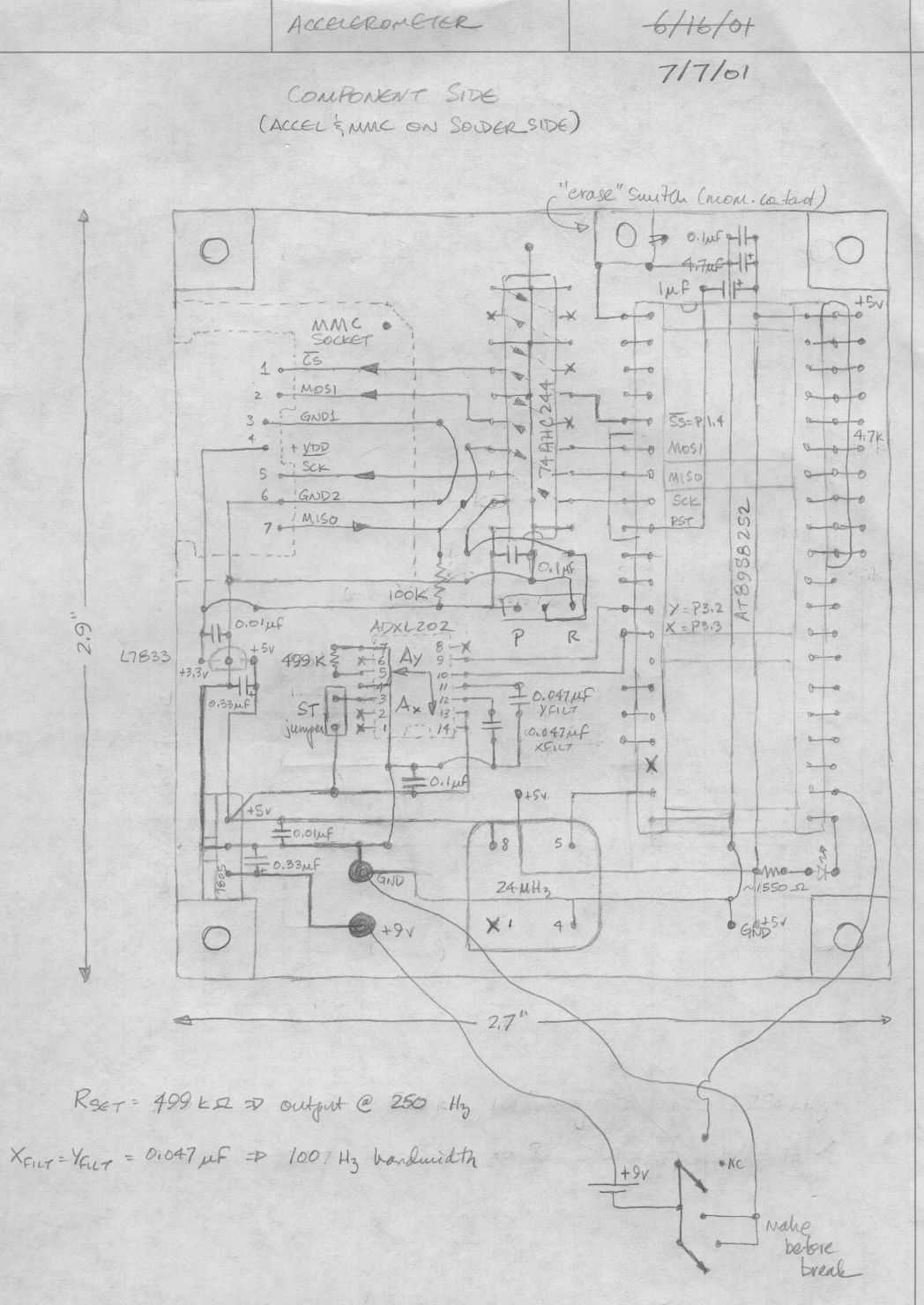
Below is a rough schematic of the layout of the accelerometer PC board looking from the component side. The microcontroller is an Atmel AT89S8252, an 8051 clone. This microcontroller is in-circuit programmable using an SPI interface. The SPI pins...

The watchdog timer includes a counter, IC3, alongside the standard retriggerable 555 timer, IC1. The counter will sound an audible alarm if the watchdog timer attempts to reset a specified number of times (8, in the case of the...