
Smoke detector using 555 timer circuit
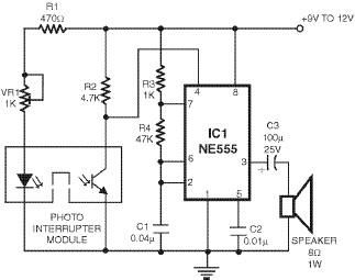
The smoke detector circuit is built around the 555 timer IC, which is a versatile and widely used component in various electronic applications. The astable configuration of the 555 timer allows it to generate a continuous square wave output, which can be used to drive a loudspeaker or any other sound-producing device. The operation begins with the photo interrupter module, which consists of an LED and a phototransistor positioned in such a way that the phototransistor detects light emitted by the LED.
In normal conditions, the LED illuminates the phototransistor, keeping its collector voltage low, which maintains the reset pin of the 555 timer in a low state. This ensures that the timer remains inactive, and the alarm does not sound. However, the presence of smoke disrupts this light path, causing the phototransistor to turn off. When this occurs, the collector voltage of the phototransistor rises, sending a high signal to the reset pin of the 555 timer. Once the reset pin receives this high signal, the timer is enabled, and it begins to oscillate, producing an audible alarm sound.
The circuit's design can be enhanced by incorporating additional features such as adjustable sensitivity through variable resistors or the addition of indicator LEDs to show the operational status of the circuit. Power supply considerations are also essential, as the circuit should be designed to operate efficiently under varying voltage levels, possibly utilizing a battery backup for reliability during power outages. Overall, this smoke detector circuit represents a practical application of the 555 timer in safety and alarm systems, showcasing its effectiveness in real-time monitoring and alerting for smoke detection.This smoke detector is designed using 555 timer circuit and some common electronic components. The photo interrupter module is used as the smoke detector, while timer 555 is wired in astable configuration as an AF oscillator for sounding alarm via a loudspeaker. In the absence of any smoke, the gap of photo interrupter module is clear and the ligh t from LED falls on the phototransistor through the slot. As a result, the collector of phototransistor is pulled towards ground. This causes reset pin 4 of IC 555 to go low. Accordingly, the timer is reset and hence the alarm does not sound. When smoke is present in the gap of the photo interrupter module, the light beam from LED to the phototransistor is obstructed. As a result, the phototransistor stops conducting and pin4 (reset) of IC 555 goes high to activate the alarm.
🔗 External reference
Related Circuits
This is a circuit diagram of an audio amplifier circuit featuring a 10W power amplifier using the TDA2003 integrated circuit from SGS Thomson. The IC is capable of delivering 10W into a 4-ohm load at a supply voltage of...
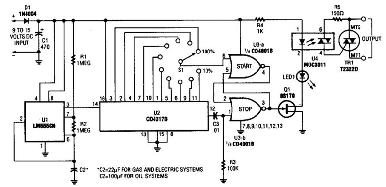
A timer (LM555CN) and decode counter are utilized to generate duty cycles ranging from 10% to 100% for controlling the operational time of a heating system. V2 operates as a decode counter that can be adjusted for duty cycles...
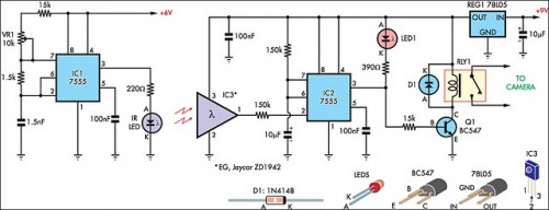
The IR detector (IC3) controls an LM 7555 CMOS timer (IC2) operating in monostable mode. When the beam is interrupted, IC2 is triggered, and its pin 3 output goes high for approximately half a second. This action extinguishes LED1...
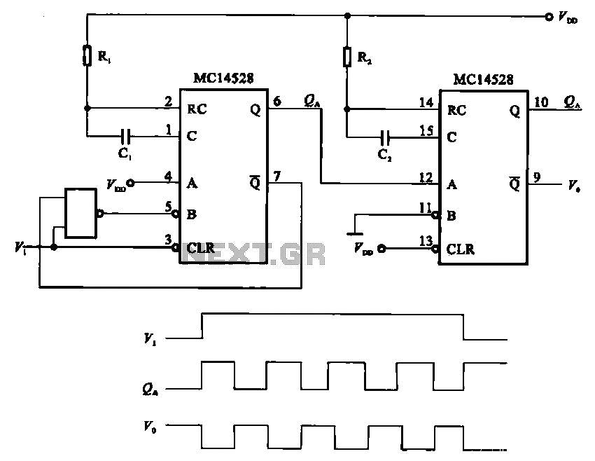
The pulse generating circuit monitors signals using monostable flip-flops. It generates a single-shot output signal based on the input pulse signal. A key signal from the monostable flip-flops is represented in a formula, with the input (V1) and output...
The circuit diagram illustrates a five-use tri-state audio logic pen utilizing components such as the CD4066 and a 555 timer. The primary elements include a multivibrator, a four-way switch (CD4066, designated as IC1), and a gate circuit formed by...
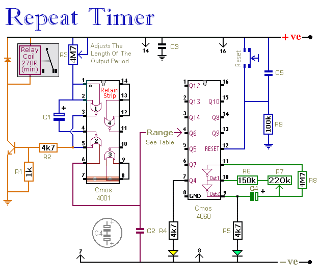
The CMOS 4060 integrated circuit (IC) features two built-in inverters located at pins 9, 10, and 11, which must be interconnected to create an oscillator. The output of this oscillator is available at Pin 9, which continuously alternates between...
Warning: include(partials/cookie-banner.php): Failed to open stream: Permission denied in /var/www/html/nextgr/view-circuit.php on line 713
Warning: include(): Failed opening 'partials/cookie-banner.php' for inclusion (include_path='.:/usr/share/php') in /var/www/html/nextgr/view-circuit.php on line 713