Smoke-gas-vapor-detector

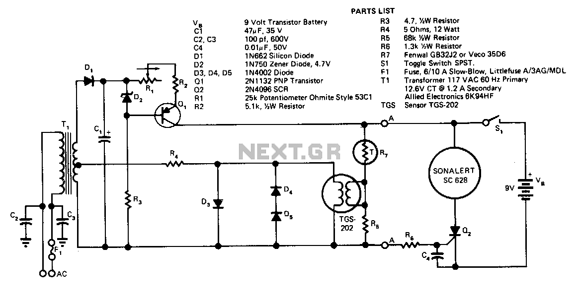
Transformer T1 provides power to the sensor's heater. Due to the sensor's high sensitivity to heater voltage, diodes D1, D4, and D5 regulate this voltage. T1, in conjunction with D1 and C2, forms a DC power supply, with current regulation managed by Q1 and adjusted by R1. The constant current from Q1 supplies a variable resistance network comprising thermistor R7 and the parallel combination of R5 and the sensor resistance. When a hazard causes the voltage at point A-A to drop, the net voltage at the SCR gate becomes positive, triggering the SCR and activating the alarm. The alarm consumes minimal current, ensuring a long battery life. Switch S1 is used to turn off the alarm and reset the SCR.
The circuit utilizes a transformer (T1) to convert AC mains voltage to a lower level suitable for the heater of the sensor. The heater's voltage is critical, as the sensor's performance is highly sensitive to changes in this voltage. To maintain a stable heater voltage, a series of diodes (D1, D4, and D5) are employed to rectify and regulate the voltage output.
The power supply configuration, which includes T1 and D1 along with capacitor C2, forms a DC power supply capable of providing a stable voltage. The current flowing through this circuit is regulated by transistor Q1, whose operation is adjusted by resistor R1. This regulation ensures that the current supplied to the sensor remains constant, which is vital for accurate sensor operation.
The sensor's resistance varies with temperature, and to account for this variability, the circuit incorporates a thermistor (R7) in conjunction with a fixed resistor (R5) to form a variable resistance network. This network allows for temperature compensation and ensures that the sensor operates within its optimal range.
In the event of a hazard that causes a voltage drop at point A-A, the SCR (Silicon Controlled Rectifier) gate receives a positive voltage, which triggers the SCR to conduct. This action activates the alarm system, which is designed to draw a minimal amount of current, thereby extending the battery life significantly. The alarm can be silenced and reset using switch S1, which interrupts the SCR's conduction path, allowing the system to return to its normal operational state.
Overall, the described circuit provides a robust solution for monitoring temperature-sensitive applications, ensuring reliable operation while maintaining energy efficiency.Transformer T1 supplies power to the heater of the sensor. Since the sensor is fairly sensitive to heater voltage, diodes Da, D4, and D5 regulate the heater voltage. Tl, together with D1 and CZ, forms a de power supply, whose current is regulated by Q1 and adjusted by Rl.
The constant current from Ql feeds a variable resistance, consisting of thermistor R7 and the parallel combination of R5 and the sensor resistance. When a hazard causes the voltage at A-A to drop, the net voltage at the SCR gate turns positive, triggering the SCR on and operating the alarm. The alarm draws a small amount of current, so the battery will last a long time. Switch S1 turns off the alarm and resets the SCR.