
Solar Botanicalls Sensor and Battery Boost
The proposed circuit design integrates a solar panel that serves dual purposes: it captures solar energy to charge a rechargeable battery and acts as a light sensor to monitor ambient light levels. This innovative approach is particularly beneficial for the Botanicalls project, as it allows for sustainable energy usage and real-time environmental monitoring of plants.
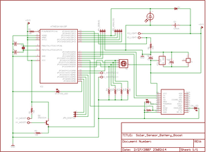
The circuit schematic features a solar panel connected to a battery management system. The solar panel is expected to generate an output voltage of approximately 3 volts under optimal sunlight conditions. This voltage is used to charge a 3 Volt rechargeable battery, which is essential for powering the Botanicalls system. The low-drop voltage regulator is included in the design to ensure that the voltage supplied to the rest of the circuit remains stable and within the operational limits of the components, despite variations in the solar panel output due to changing light conditions.
The light sensor component of the circuit is crucial for the system's functionality. It will continuously monitor the light levels and provide feedback to the Arduino microcontroller. The microcontroller will process this information to determine whether the plant needs additional light or if the solar panel is functioning efficiently. This feedback loop is important for optimizing plant care and ensuring that the Botanicalls system operates effectively.
The next phase of the project involves assembling the described sub-circuit on a test breadboard. This will allow for practical experimentation with various solar panels and battery types. The performance of each combination will be evaluated to determine the most effective setup for charging and light sensing. The Arduino microcontroller will facilitate data collection and analysis, enabling adjustments to the circuit as needed based on real-time performance metrics.
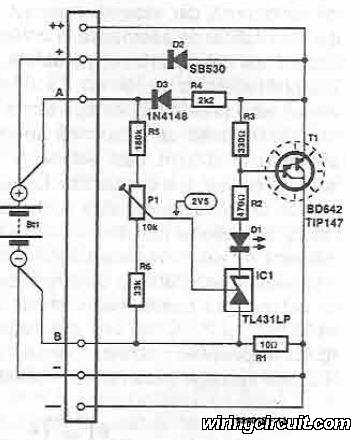
Overall, the integration of a solar panel as a charging and sensing mechanism represents a significant advancement in the Botanicalls project, promoting energy efficiency and enhancing the overall functionality of the system.Working on augmenting Botanicalls with a solar panel that will act as both a light sensor and a battery charger for each plant in the project. The full circuit schematic is above with a detail showing the solar charge and sensor connections below.
We`re planning to try a 3 Volt rechargeable battery with a low-drop voltage regulator for our power supply. Click on each of the images for a full-size graphic. The next project steps will be to build the sub-circuit on a test breadboard, to see how well different panels are able to charge various batteries while sensing light values using the Arduino microcontroller. 🔗 External reference
Related Circuits
20W Bridge Audio Amplifier kit, based on the TDA2005 IC, a class B dual audio amplifier, specifically designed for car radio applications etc. More: Power supply - 18 VDC Output power - 20 W, 4 Ω IC built in Thermal Shut-down,...

This circuit provides a regulated output of either 4.8 V or 7.2 V at a current of 15 mA, utilizing a 3 V input sourced from a bank of photocells. A load resistor (Rl) of 453 kΩ is required...
This circuit explains alternate wireless switching using an ultrasonic sensor. The distance of the switching range should be more than 10 meters. The described circuit employs an ultrasonic sensor to facilitate wireless switching, allowing for the activation or deactivation of...
This voltage regulator for devices that utilize solar cells is straightforward and requires only a few electronic components. When a rechargeable energy storage device is employed, the voltage regulator circuit facilitates charging when the output voltage of the cell...
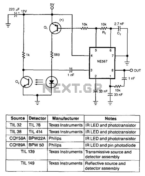
Using only an 8-pin integrated circuit (IC) and a few discrete components, an infrared optical interrupter can be constructed. The NE567 tone decoder includes all necessary circuit elements: a local oscillator, a phase-locked loop (PLL) decoder, and a 100-mA...
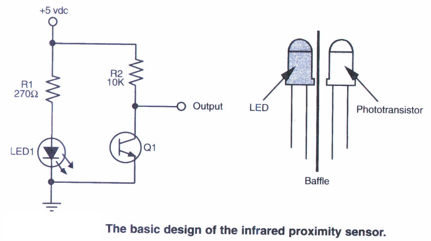
This section provides step-by-step instructions along with images for constructing an infrared (IR) proximity switch. As this is a straightforward circuit, only the schematic for the sensor is presented here. The objective of this tutorial is to assist others...
Warning: include(partials/cookie-banner.php): Failed to open stream: Permission denied in /var/www/html/nextgr/view-circuit.php on line 713
Warning: include(): Failed opening 'partials/cookie-banner.php' for inclusion (include_path='.:/usr/share/php') in /var/www/html/nextgr/view-circuit.php on line 713