
solar charger picaxe
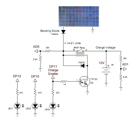
The PICAXE solar panel battery charge controller is designed to manage the charging process of batteries using solar energy. This system typically involves several key components: the solar panel, battery, PICAXE microcontroller, and various electronic components such as resistors, diodes, capacitors, and possibly a voltage regulator.
The solar panel converts sunlight into electrical energy, which is then directed to the charge controller. The PICAXE microcontroller is programmed to monitor the voltage levels of the solar panel and battery, ensuring that the battery is charged efficiently without overcharging. The programming of the PICAXE involves writing a code that dictates how the microcontroller responds to different voltage levels, controlling the flow of current to the battery.
In terms of circuit design, the solar panel is connected to the input of the charge controller. A diode is often included in the circuit to prevent reverse current flow from the battery back to the solar panel during low light conditions. The output of the charge controller connects to the battery, which stores the energy for later use.
Additional components may include a voltage divider to measure the battery voltage accurately, and potentially a display or LED indicators to show the charging status. The entire system can be housed in a protective enclosure to safeguard against environmental factors.
The programming of the PICAXE can include features such as temperature compensation, where the charging parameters adjust based on the battery temperature, and load control, which can disconnect the load if the battery voltage drops below a certain threshold. This ensures the longevity of the battery and optimizes the charging process, making the system efficient and reliable for renewable energy applications.Construction and programming PICAXE solar panel battery charge controller.. 🔗 External reference
Related Circuits
The 220-240V AC mains source is stepped down to 9V AC by transformer X1. The transformer output is rectified by diodes D1 through D4 connected in a bridge configuration, with the positive DC voltage wired directly to the charger's...
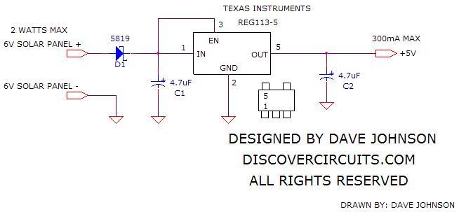
The simple circuit below regulates the voltage from a 6V solar panel to a fixed +5V. This voltage can be supplied to any cell phone or USB-connected portable device to charge its battery. The circuit utilizes a Reg113-5 voltage...
A regular charger was tested and found to consume 13mA with no load. It features an integrated power LED, which significantly contributes to standby current consumption. However, since the cigarette lighter socket is powered only when the engine is...
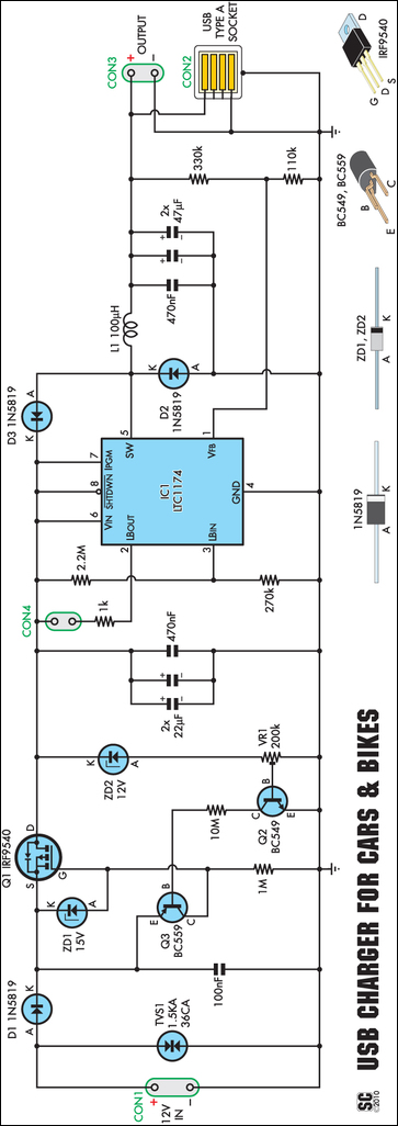
A charger is essential for charging a 12 Volt battery from a 12 Volt source due to the typical voltage variation between 11 Volt and 15 Volt. A battery requires a controlled charge current and voltage, which cannot be...
There are two types of solar automatic tracking controllers. One type utilizes a Schmitt trigger light control, which consists of a light sensor and a Schmitt trigger or monostable trigger. The second type employs two light sensors and two...
Solar cell type Maximum efficiency Practical efficiency Notes Selenium, polycrystalline 0.7% - 1883, Charles Fritts Silicon, single crystal - 4% 1950's. Solar cells, also known as photovoltaic cells, convert sunlight directly into electricity through the photovoltaic effect. The efficiency of...
Warning: include(partials/cookie-banner.php): Failed to open stream: Permission denied in /var/www/html/nextgr/view-circuit.php on line 713
Warning: include(): Failed opening 'partials/cookie-banner.php' for inclusion (include_path='.:/usr/share/php') in /var/www/html/nextgr/view-circuit.php on line 713