
Solenoid Tutorial
The circuit design incorporates a bypass diode (D1) to protect the Arduino from the inductive kickback generated by the solenoid. When the solenoid is energized, the diode remains reverse-biased, preventing current flow. However, upon deactivation, the inductive nature of the solenoid attempts to maintain current flow, which results in a voltage spike. D1 provides a pathway for this current to recirculate until the magnetic energy dissipates, effectively clamping the voltage to a safe level.
The use of the IRF640 as the switching element allows for efficient control of the solenoid. This FET is selected for its high current capacity and voltage tolerance, but any suitable N-channel FET could be used, provided it meets the operational requirements. The circuit emphasizes the importance of ensuring that the gate voltage is either fully on or fully off to avoid excessive power dissipation and potential damage to components.
In applications where an NPN bipolar transistor is preferred, careful attention must be given to the transistor's gain to ensure proper saturation, which is critical for reliable operation. The optoisolator, while providing electrical isolation, complicates the design and is not necessary for basic operation, allowing for a simplified circuit that directly controls the solenoid with the Arduino.
Overall, this circuit design emphasizes safety and reliability, protecting sensitive microcontroller components from the potentially damaging effects of inductive loads like solenoids.Not drive a solenoid directly from your Arduino. It requires more current than you can provide and produces destructive voltages when it is switched off. There is a simple solution. The solenoid I was testing with is a 12 volt solenoid the size of my thumb. It passes 1 amp of current when turned on and becomes uncomfortably warm to hold if left on. Your Arduino can only pass about 40mA from a pin. You probably will need to measure your solenoid before you can choose components. Use your ammeter to measure the solenoid`s current draw when you power it directly from the power supply. A solenoid is a coil of wire with a magnetic core. This is virtually identical to a large inductor, so it should not be surprising that they have inductance.
i. e. Once a current is moving in the solenoid it will attempt to continue moving that current. This can be fatal to your digital device when it switches off the solenoid and the solenoid creates a voltage across its leads large enough to either move the current, arc through the air, or burn through a semiconductor. The solution is to provide an easy and safe path for the current to flow until it dissipates the energy stored in the magnetic fields of the solenoid.
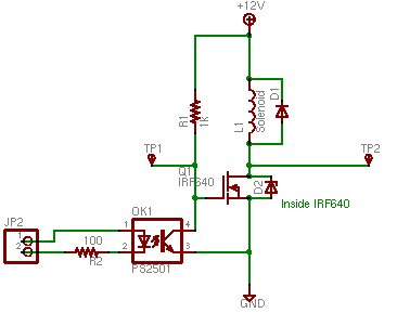
Most of the schematic is test point labels and my extra protection circuitry for testing the bad configurations. You really only need D1, L1, Q1, and a resistor to be named later. The schematic shows a bypass diode, D1. When the solenoid is on or idle this diode will not conduct. Its top terminal will be at a higher or equal voltage. When the solenoid is turned off and tries to continue forcing current downward, this current can flow back up through D1 until the energy is dissipated.
This will clamp TP2 to no more than 13v or so. This diode must be able to pass whatever current passes through the solenoid and have a reverse breakdown voltage of at least the power supply voltage. The IRF640 shown in this circuit operates as if it has a zener diode in parallel. A zener diode acts like a regular diode until its reverse voltage exceeds a specified voltage, then it conducts in the reverse direction.
In this case the IRF640 acts like a 200V zener, so once the inductive kick hits 200V it will pass through the FET to ground. This could be sufficient, but I don`t care for it as a protective measure: The IRF640 is a field effect transistor.
These can be operated as voltage controlled switches. If the gate voltage is 0 the switch will be off. If the gate voltage is high then the switch will be on, about like a 0. 18ohm resistor. Do not let the gate voltage be in between if you are using the transistor as a switch, it can partially conduct, dissipate a lot of energy, and overheat. The FET shown is overkill for this circuit, it can pass 18 amps and withstand 200 volts. It was only selected because I pulled it out of a ruined UPS. You could use any N channel FET that will withstand your voltage and currents. Plan a factor of two safety margin if you can. You could also use an NPN bipolar transistor. You need to make sure that you saturate the transistor. That is. 40ma (your arduino current) times the current gain of the transistor (hfe) needs to be larger than your solenoid`s current.
I`d shoot for twice as large to be safe. These will not have the second safety diode behavior, so don`t screw up D1. The schematic shown is from my test circuit where I knew I would operate without the bypass diode. OK1 is an optoisolator which completely separates the Arduino from the test circuit electrically. Somewhat unfortunately, I connected it as an inverter, so the solenoid is on unless the arduino pin is set as an output and turned on. I don`t recommend that. You do not need the optoisolator. You can drive the gate of the FET with the digital pin directly and omit R2, R1, and OK1. You do need to connect your Arduino ground to the ground shown on the circuit and also place a 10k resistor f
🔗 External reference
Related Circuits
Colour TV Camera Tutorial - Block Diagrams - Electronics Circuit and Tutorials - Hobby Science Projects - Modulation allows low-frequency audio signals to be transmitted over long distances. This is achieved by superimposing the low-frequency audio signal onto a...

The schematic for this project is designed to be very simple, utilizing a minimal number of components to keep costs and assembly time low. The primary components in the schematic include the PIC 18F452 microcontroller, a tilt sensor, and...
The bipolar junction transistor is one of the cornerstones of modern solid-state electronics. Understanding the basics of this important active device is essential. The Bipolar Junction Transistor (BJT) initiated the revolution in solid-state electronics during the 1960s. Although discrete...
This is a brief guide to help users begin with KiCAD. The tutorial focuses on a simple astable multivibrator circuit utilizing the 555 timer IC. The astable multivibrator circuit using the 555 timer IC is a fundamental electronic configuration that...

This tutorial provides information related to sensor amplifiers, schematics, and noise. It presents a discussion around sensors and their outputs. Sensor amplifiers are critical components in various electronic systems, especially in applications where signals from sensors need to be conditioned...

Energia is a rapid prototyping platform designed for the Texas Instruments MCU Launchpad. It is built on the principles of Wiring and Arduino and utilizes the Processing IDE. Energia offers an accessible environment for developing applications with Texas Instruments microcontrollers. By...