
Sound activated relay
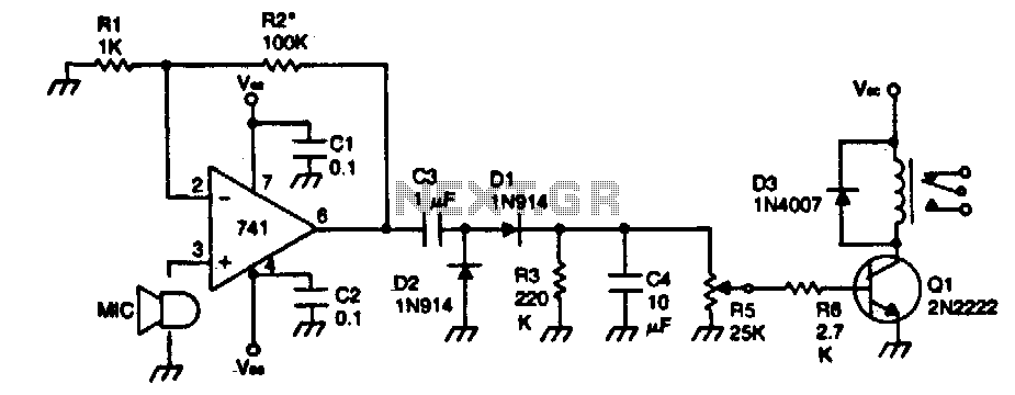
The circuit described operates as a sound-activated relay switch. Initially, the device is in a dormant state, consuming minimal power until it detects an audible sound. The core of the circuit is the 741 operational amplifier, which is configured as a non-inverting amplifier. This configuration allows the circuit to amplify the incoming audio signal while maintaining its phase, which is critical for accurate signal processing.
The gain of the amplifier is approximately 100, determined by the ratio of resistors R1 and R2. The gain can be adjusted by changing the resistance value of R2, which allows for flexibility depending on the sensitivity required for sound detection. A higher value of R2 increases the gain, making the circuit more responsive to quieter sounds.
After amplification, the audio signal is rectified to convert the AC signal into a DC level. This process is essential for the subsequent stages of the circuit, where the rectified signal is filtered using R4 to smooth out any fluctuations, resulting in a stable DC output. This stable DC level is crucial for driving the next component, which is a relay.
Resistor R5 plays a pivotal role in setting the threshold for the audio level required to activate the relay. By adjusting R5, the user can define the minimum sound level that will trigger the relay, allowing for customization based on the specific application. When the audio level exceeds this threshold, the relay is activated, enabling it to control other devices or circuits as intended.
Overall, this sound-activated relay circuit provides a practical solution for applications requiring automatic activation based on sound detection, making it suitable for various electronic projects.The device remains dormat (in an off condition) until some sound causes it to tum on. The input stage is a 741 operational amplifier connected as a noninverting follower audio amplifier. Gain is approximately 100. To increase gain raise the value of R2 The amplified signal is rectified and filtered to a dc level by R4. Then R5 is set to the audio level desired to activate the relay. 🔗 External reference
Related Circuits
This circuit is designed for use with inductive pick-up elements and dynamic microphones. Most soundcards feature a line input and a separate input for electret (condenser) microphones. To connect an inductive tape recorder head or a dynamic microphone, an...
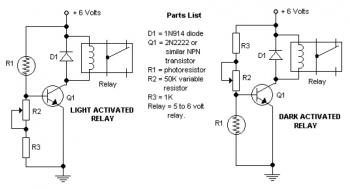
The potentiometer adjusts the trigger level. The diode in the circuit diagram is specified as 1N914, which is suitable for light-duty relays; however, since the 1N914 is a signal diode, it is not ideal for this application. A 1N4001...
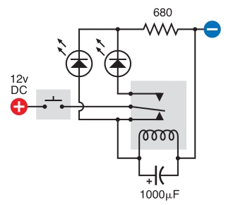
The intended result is for the relay to oscillate and the LEDs to flash when the button is pressed. However, when the button is pressed, the leftmost LED lights constantly, and nothing else happens. There is voltage across the...
Probes or contacts may utilize a non-reactive metal. Gold or silver plated contacts from an old relay may be used; however, a cost-effective alternative is to wire alternate copper strips from a piece of veroboard. These will eventually oxidize,...

An NPN bipolar transistor is typically utilized for relay switching, particularly with 12V coil-rated relays, as it helps maintain circuit separation. A diode is also added to prevent issues. The necessity of driving the relay with a transistor depends...

This circuit utilizes the Mitsubishi M65830 Digital Delay chip, which has proven to be simple and effective for applications requiring a fixed delay. The serial data necessary for achieving various delay settings is not readily available and would significantly...