
Sound-activated switch
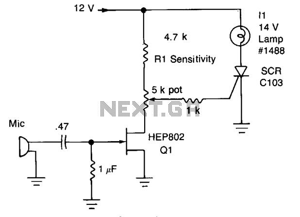
The circuit described involves a signal detection mechanism that utilizes a silicon-controlled rectifier (SCR) to control the illumination of lamp II based on the amplitude of the input signal. The threshold for triggering the SCR is set at approximately 0.7 volts, which is determined by the resistor Rl. When the input signal, which is derived from an audio source such as a microphone, exceeds this threshold, the SCR is activated, allowing current to flow and thus lighting lamp II.
The audio signal from the microphone is first processed by transistor Q1, which functions as an amplifier. The purpose of Q1 is to increase the amplitude of the audio signal to a level suitable for further processing. This amplification stage is crucial, as it ensures that even low-level audio signals can effectively trigger the SCR when they reach the required voltage threshold.
The design may include additional components, such as capacitors for AC coupling and filtering, which help to stabilize the signal and prevent noise from affecting the performance of the circuit. The use of Rl is also significant, as it not only sets the trigger level for the SCR but may also influence the response time of the circuit, determining how quickly the lamp can turn on or off in response to signal changes.
Overall, this circuit exemplifies a simple yet effective method for controlling a load (lamp II) based on the amplitude of an audio signal, utilizing basic electronic components to achieve the desired functionality. Peaks of signal (adjusted by Rl) greater than about 0.7 volts trigger the SCR and light lamp II. The audio from Mic is amplified by Ql. 🔗 External reference
Related Circuits
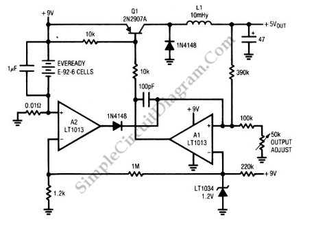
A circuit of a low-power switching regulator is illustrated in the schematic diagram below. This circuit can provide an output voltage of 5V from a 9V source. The efficiency... The low-power switching regulator circuit is designed to convert a higher...
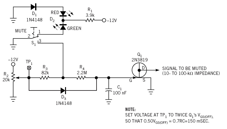
This simple circuit is a line-level audio signal muting switch based on a soft-action power on/off process. When the S1 switch is closed, R4, C1, and Q4 JFET are activated to mute the audio signal. The circuit operates by utilizing...
After searching for a few days, a solution for this idea has not been found. A switch panel is being created in the dashboard containing four switches. The switch panel design for the dashboard involves integrating four switches that can...
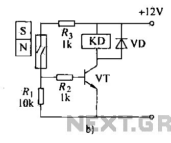
The automatic weapon features a magnetic switch circuit that is simple, reliable, has a low failure rate, and offers good versatility. It can be used to output performance or convert mechanical displacement. The circuit diagram utilizes a Hall switch...
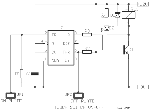
This type of sensor switch is ideal for creating touch-operated bells and buzzers in small toys, which function for a limited duration before automatically shutting off. The trigger's input impedance is very high, allowing the touch sensor switch to...
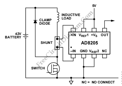
The AD8205 can be utilized to create a high-side current sensing circuit with a low-side switch. In this configuration, an inductive load (such as a solenoid) and a resistive shunt are incorporated. The resistive shunt is positioned on the...