
Sound Controlled Toggle Switch
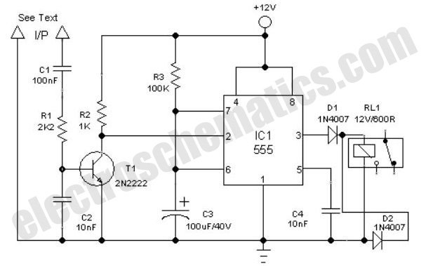
This circuit utilizes a sound sensor to detect specific audio frequencies, such as those produced by a whistle or clap. The sound sensor is typically an electret microphone or a dedicated sound detection module that converts sound waves into electrical signals.
Upon receiving a sound signal, the sensor outputs a corresponding voltage level, which is then fed into a microcontroller or a comparator circuit. The microcontroller is programmed to recognize the specific sound pattern (whistle or clap) and toggle the output state of a digital pin accordingly. The output can drive an LED, relay, or any other load, providing a visual or functional response to the detected sound.
The toggle mechanism can be implemented using a flip-flop configuration, which ensures that the output state alternates between high and low each time the sound signal is detected. This allows for a simple on/off control based on auditory commands.
Power supply requirements for the circuit typically include a DC voltage source, which can range from 5V to 12V, depending on the components used. Proper decoupling capacitors should be employed near the power pins of the microcontroller to minimize noise and ensure stable operation.
For optimal performance, the sound sensor should be positioned to minimize background noise interference, and the sensitivity can often be adjusted via a potentiometer included in the circuit. Additionally, it may be beneficial to implement debounce logic in the software to prevent false triggering from unintended sounds.
Overall, this sound-activated toggle switch circuit offers an innovative solution for remote control applications and can be adapted for various use cases, including home automation and assistive technology.Here is a simple toggle switch that can be operated through sound signals such as whistle or clap. The output of the toggle remains either low or high unti.. 🔗 External reference
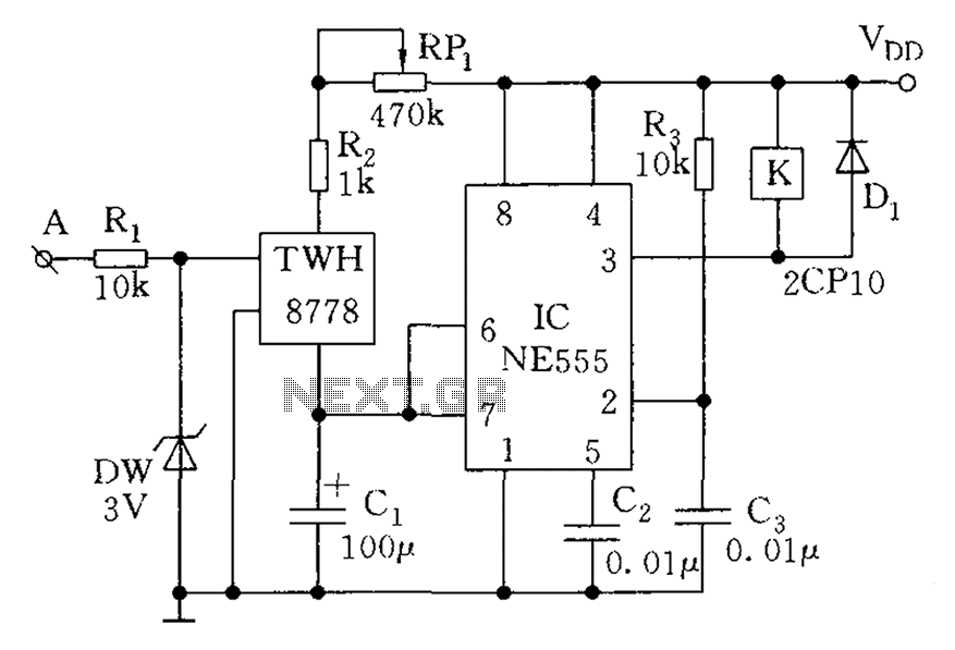
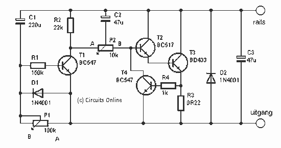
Related Circuits
The count switching circuit consists of an electronic switch and a pulse delay circuit for control. The count switching circuit is designed to manage the switching of signals in a controlled manner. The electronic switch serves as the primary component...
This switch allows the model train at such a station to automatically slow down. The train stands for a certain amount of time and then slowly pulls back. You do not need to stop the train. The relatively simple...
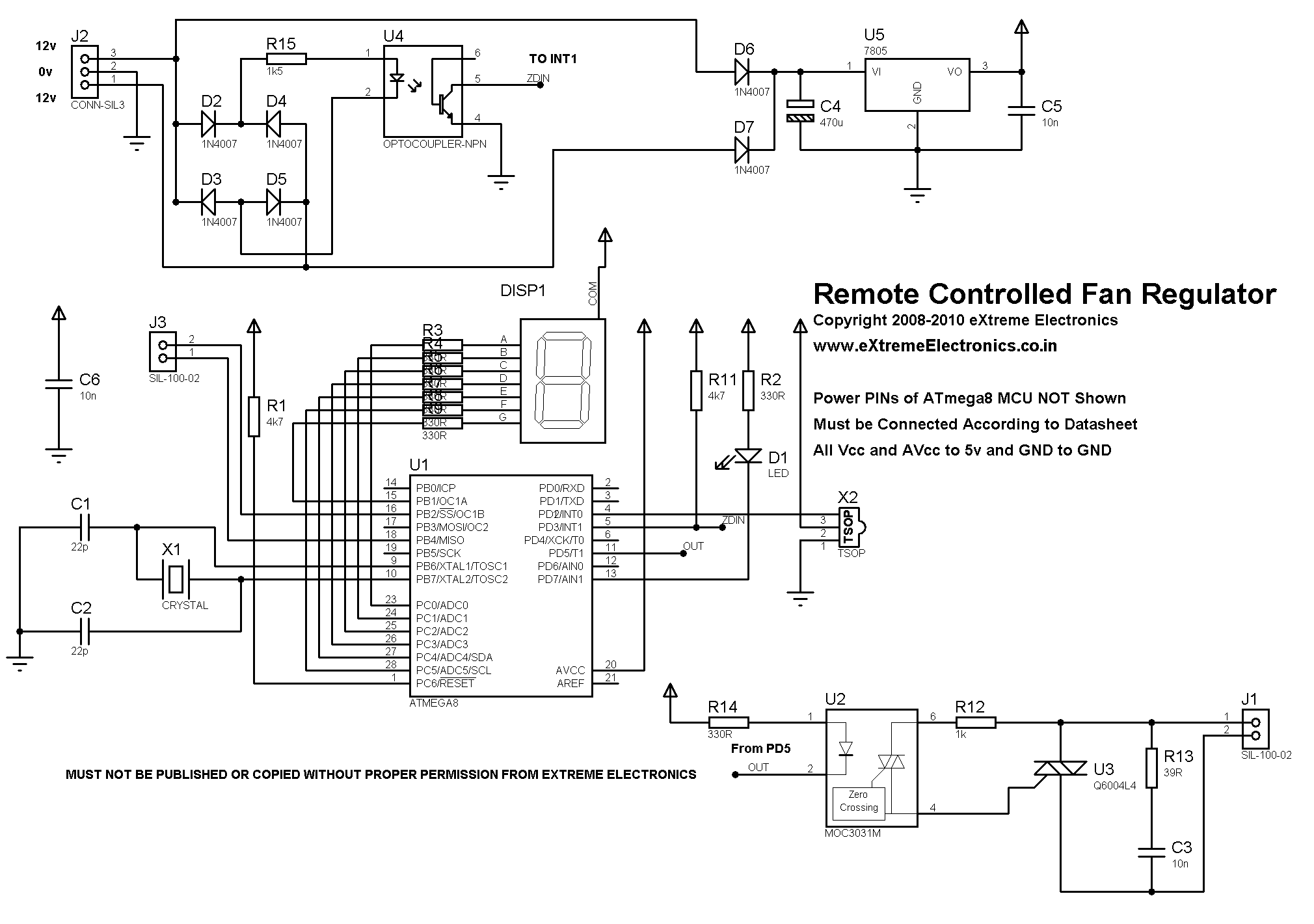
A detailed DIY remote-controlled AC fan regulator with 10-stage speed control. It is built using the ATmega8 microcontroller, and includes full source code and PCB layout. This project involves designing a remote-controlled AC fan regulator that allows users to adjust...
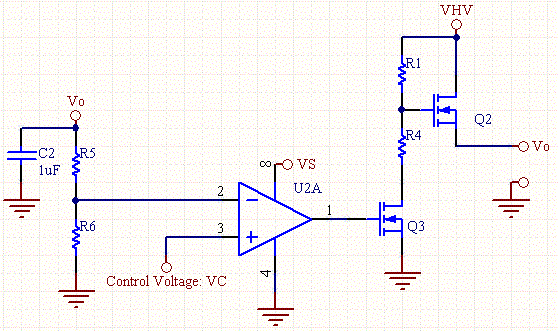
The drawback of the circuit mentioned is that the operational amplifier (op-amp) supply is connected to the high voltage (HV) supply. Most op-amps are limited to approximately 30V for their supply voltage, which prevents the circuit from functioning with...
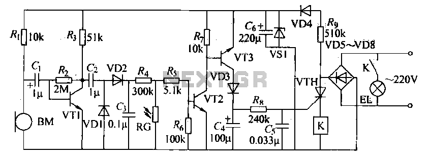
The voice circuits discussed in this section operate such that during daylight or in bright conditions, the voice-activated switch remains off, preventing the lamp from lighting. Conversely, in low-light conditions or at night, the sound control switch is activated....
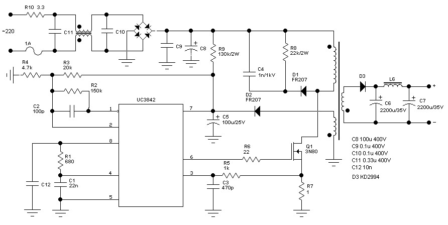
The schematic diagram originates from a 60 Watt Switching Power Supply. It details a power supply designed for a 70W stereo amplifier, utilizing the KA2S0880 chip, which encompasses all necessary components for constructing the primary section of the power...
Warning: include(partials/cookie-banner.php): Failed to open stream: Permission denied in /var/www/html/nextgr/view-circuit.php on line 713
Warning: include(): Failed opening 'partials/cookie-banner.php' for inclusion (include_path='.:/usr/share/php') in /var/www/html/nextgr/view-circuit.php on line 713