
Sound-effects-generator
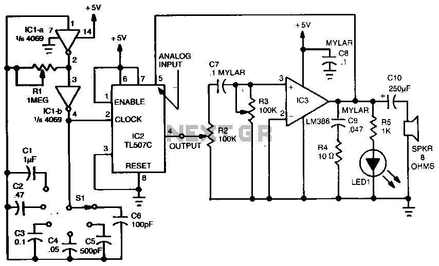
A variable dock-pulse generator consists of two sections of IC1, which is a 4069 CMOS hex inverter, along with resistor R1, switch S1, and capacitors C1 through C6. By adjusting R1 and switching one of the capacitors into the circuit, the clock's pulse rate can be varied across a wide range. The TL507C is utilized to convert analog signals, specifically the output from IC3, an LM386 audio amplifier, into digital signals.
The conversion is achieved through the single-slope method, which involves comparing an internally generated ramp signal with the analog input signal and a 200 mV reference voltage. The square-wave output from the analog-to-digital converter is directed to IC3 through a network comprising resistors R2, R3, and capacitor C7. Resistor R2 is responsible for controlling the amplitude of the pulses. Resistor R3 and capacitor C7 form a variable tone-control filter and a differentiator circuit that transforms a square wave into a spiked waveform. This waveform is then amplified by IC3, and the resulting output is fed back into the analog input of IC2, as well as to an 8-ohm speaker. By adjusting R1 and selecting one of the six capacitors with switch S1 to vary the clock frequency, and by modifying resistors R2 and R3, a wide variety of sounds can be produced.
The variable dock-pulse generator operates as a versatile audio signal processor. The use of the 4069 CMOS hex inverter allows for efficient signal manipulation, while the adjustable components enable fine-tuning of the output characteristics. The TL507C's single-slope analog-to-digital conversion method is particularly effective for generating precise digital representations of the analog signals, ensuring high fidelity in sound reproduction.
The network of R2, R3, and C7 plays a crucial role in shaping the output waveform. The amplitude control provided by R2 ensures that the output signal remains within the desired range, preventing distortion. Meanwhile, the combination of R3 and C7 as a tone-control filter allows for dynamic adjustments to the frequency response, enhancing the overall audio quality. The differentiator function of the circuit adds sharp transients to the output waveform, contributing to a more complex and engaging sound.
The feedback loop from IC3 to the analog input of IC2 facilitates an interactive system where the output influences the input, allowing for real-time modulation of the sound produced. This feedback mechanism, combined with the adjustable parameters, empowers users to explore a broad spectrum of audio effects and tones, making the variable dock-pulse generator an invaluable tool for sound design and experimentation.A variable dock-pulse generator is made up of two sections of IC1 (a 4069 CMOS hex inverter). Rl, Sl, and capacitors Cl through C6. By adjusting Rl and switching one of the capacitors into the circuit, the clock"s pulse rate can be varied over a wide range. The TL507C converts analog signals-in this case the output of IC3, an LM386 audio amplifier -into digital signals.
The conversion is accomplished using the single-slope method; it involves comparing an internally generated ramp signal to the analog input signal and a 200-mV reference voltage. The square-wave output from the aid converter is fed to IC3 through a network consisting of R2, R3, and C7.
Resistor R2 controls the amplitude of the pulses. Resistor R3 and capacitor C7 form a variable tone-control filter and a differentiator circuit that converts a square wave into a spiked waveform. That waveform is amplified by IC3, and the resulting output is fed back into the analog input of IC2, as well as to an 8-0 speaker.
By adjusting Rl and selecting one of the six capacitors with Sl-thus varying the clock frequency-and by varying R2 and R3, you can produce many sounds. 🔗 External reference