
sound generator
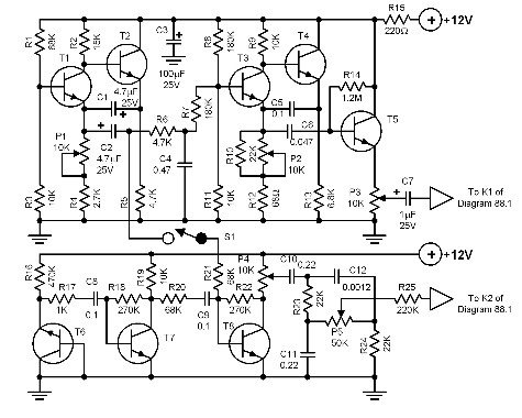
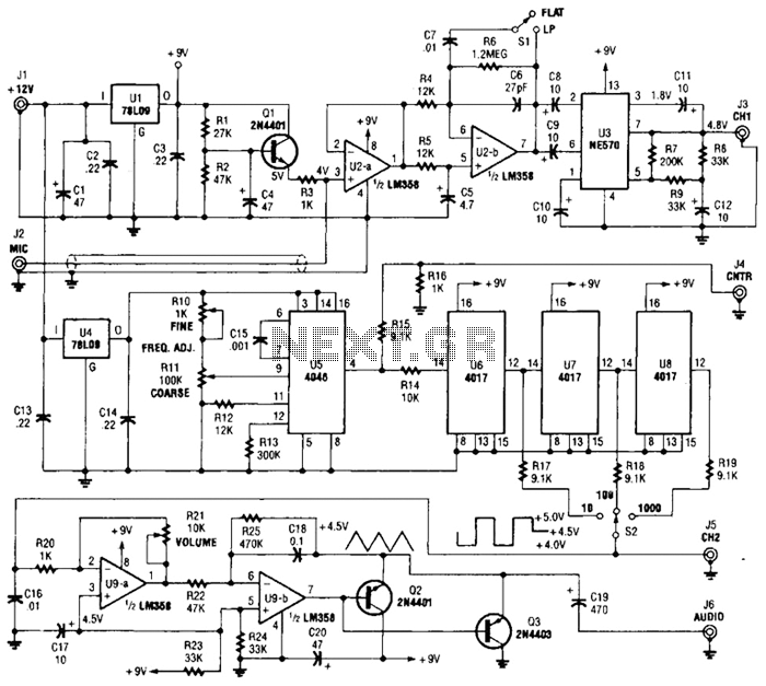
This circuit primarily consists of two vibrato generators and a tone generator, which work in conjunction to create a wide range of auditory experiences. The first vibrato generator utilizes transistors T1 and T2 to modulate the output frequency of the tone generator, made up of transistors T3 and T4. The frequency adjustment feature provided by potentiometer P2 allows for fine-tuning, enabling users to explore different sound textures.
The second vibrato generator, utilizing transistors T6 and T10, functions similarly to the first, adding another layer of modulation to the sound output. The noise generation is specifically handled by T6, which produces raw sound waves that are then amplified by transistors T7 and T8. This amplification is crucial for achieving a robust sound output, ensuring that the generated noise can be effectively utilized in the overall sound synthesis.
Potentiometers P3, P8, and P4 are strategically incorporated to control the amplitude of the output signal. This feature allows users to modify the loudness and intensity of the sound effects, providing a customizable audio experience. Furthermore, potentiometers P5, P9, and P10 are dedicated to shaping the noise envelope and strength, allowing for intricate control over the dynamics of the sound produced.
The final mixed output, which combines both tone and noise signals, is accessible at the emitter of transistor T14. This point in the circuit serves as a critical juncture where all generated sounds converge, ready for amplification or further processing. The design encourages experimentation with the various potentiometer settings, fostering creativity and exploration in sound design. This flexibility makes the circuit not only a tool for sound generation but also an engaging platform for audio experimentation, capable of producing a vast array of unique sound effects.The construction of this quite complicated circuit will be awarded with the joy of generating almost unlimited sound effects. The circuit can produce different sounds like the heavy chopping of a helicopter s blades up to the fine chirping of a bird.
A vibrato generator (T1 and T2) modulates a tone generator (T3 and T4). The frequency of the vibr ato generator can be varied through P2. A second vibrato generator is also built (T6. T10) and has the same function as the first one described. The noise sound is produced by T6 while transistors T7 and T8 amplify the generated noise sound. The potentiometers P3, P8 and P4 influence the amplitude of the generated signal and create the desired sound effect. Potentiometers P5, P9, P10 produce the desired noise envelope and strength. The mixed tone and noise signals appear at the emitter of T14. Experimenting with different potentiometer settings will certainly produce hours of enjoyment and lots of unique sound effects.
🔗 External reference
Related Circuits
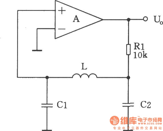
A square-wave generator utilizing an LC circuit can achieve improved frequency stability, as illustrated in the accompanying chart. This three-terminal capacitor oscillator is capable of generating a square wave, with an operational amplifier serving as the active component. The square-wave...
The circuit illustrated produces a brief sequence of rapidly alternating tones, reminiscent of the sounds associated with advanced computers, often featured in science fiction. This circuit was designed for the composition "Be Quite Still" by the band "The Cassettes."...
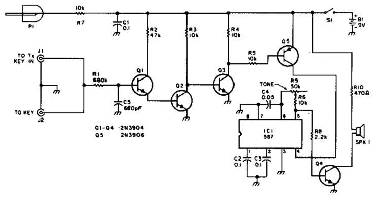
For use with low-power transmitters that require a positive keying voltage. The transistors Q1, Q2, and Q3 are configured as a switching amplifier. When the key is pressed, the collector of Q3 is pulled to ground, which activates Q5...

A function generator virtual oscilloscope designed using a sound card serves as a multi-functional device, incorporating a microcontroller-based function generator. This project represents the implementation of a graduation thesis. A function generator typically generates various voltage waveforms, such as...
One section of the precision audio frequency generator utilizes an electret microphone element to capture audio from the piano. The captured signal is processed and transmitted to one channel of a dual-trace oscilloscope. The other section of the circuit...
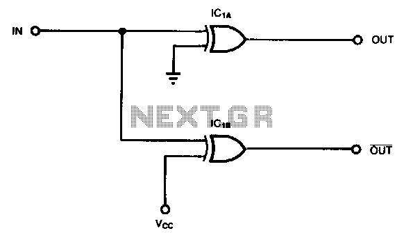
Some applications, such as driving three-state buffers for data multiplexers or for biphase clocks in high-speed systems, require complementary signals with minimal time skew and nearly simultaneous transitions. In this context, XOR gates serve as both inverting and non-inverting...