
Sound-level-meter
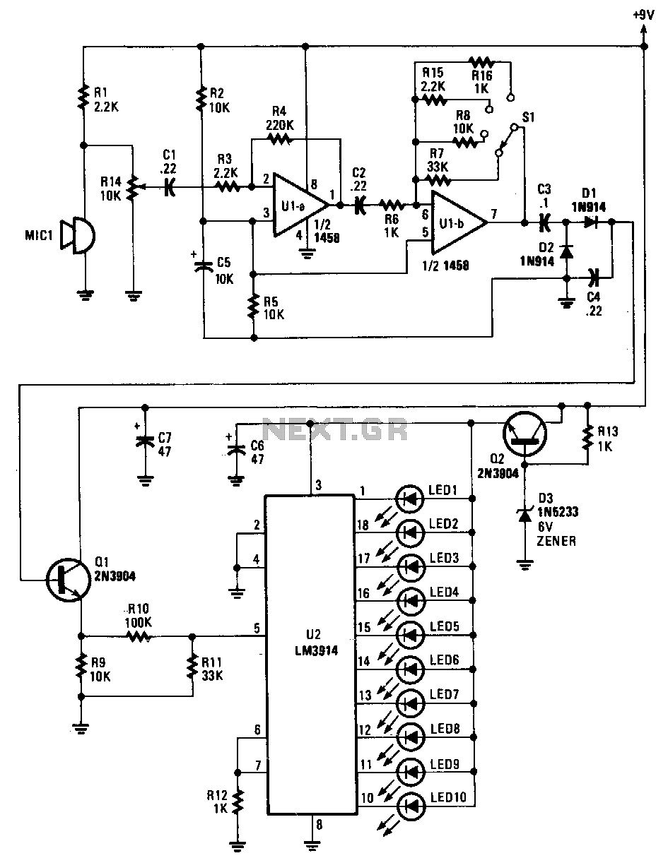
Sounds are captured by MIC1 and sent to the input of the first operational amplifier (op-amp). The signal is subsequently directed to the input of the second op-amp, U1B, where it is amplified by a factor ranging from 1 to 33, depending on the position of the range switch, S1. When the range switch is set to position A, resistors R6 and R7 are configured as 1 kΩ and 33 kΩ, respectively, resulting in a gain of 33. In position B, the gain is 10; in position C, the gain is 22; and in position D, the gain is 1. As the voltage of the input signal at pin 5 of U2 varies, one of ten LEDs will illuminate to indicate the corresponding input voltage level. At the lowest operating input level, U2 outputs a signal at pin 1, activating LED1. Conversely, the highest input level, approximately 1.2 V, causes LED10 to light up.
The circuit operates by utilizing a microphone (MIC1) to transduce sound waves into electrical signals. These signals are initially amplified by the first op-amp, which is configured to provide a preliminary gain before the signal is further processed. The second op-amp, U1B, is crucial for adjusting the overall gain based on the selected range. The range switch (S1) allows for flexibility in gain settings, enabling the circuit to accommodate various input signal levels.
The gain adjustments are achieved through the selection of resistor values R6 and R7, which form a voltage divider network. In position A, the high gain of 33 is suitable for weak input signals, while the lower gain settings in positions B, C, and D allow for optimal performance with stronger signals. The gain settings are critical for ensuring that the output signal remains within the operational range of U2, which drives the LED indicators.
The output from U2 is designed to visually represent the input voltage level using a series of ten LEDs. Each LED corresponds to a specific voltage range, providing immediate feedback on the signal strength. This feature is particularly useful for monitoring audio levels in various applications. The lowest input level activates LED1, indicating minimal signal presence, while LED10 is activated at the maximum input level of approximately 1.2 V, signaling the highest signal strength. This LED feedback mechanism enhances user interaction with the circuit, allowing for quick assessments of audio input levels without the need for additional measuring instruments.Sounds are picked up by MIC1 and fed to the input of the first op amp. The signal is then fed to the input of second op amp Ulb, where it is boosted again by a factor of between 1 and 33, depending upon the setting of range switch Sl. With the range switch set in the A position, R6 is 1 K!:J and R7 is 33 K!:J, so that stage has a gain of 33.
In the B position, the gain is 10 !:J; in the Cposition, the gain is 22 !:J; and in the D position the gain is 1 !:J. As the signal voltage fed to the input of U2 at pin 5 varies, one of ten LEDs will light to correspond with the input-voltage level.
At the input"s lowest operating level, U2 produces an output at pin 1, causing LEDl to light. The highest input level presented to the input of U2, about 1.2 V, causes LED10 to turn on. 🔗 External reference
Related Circuits
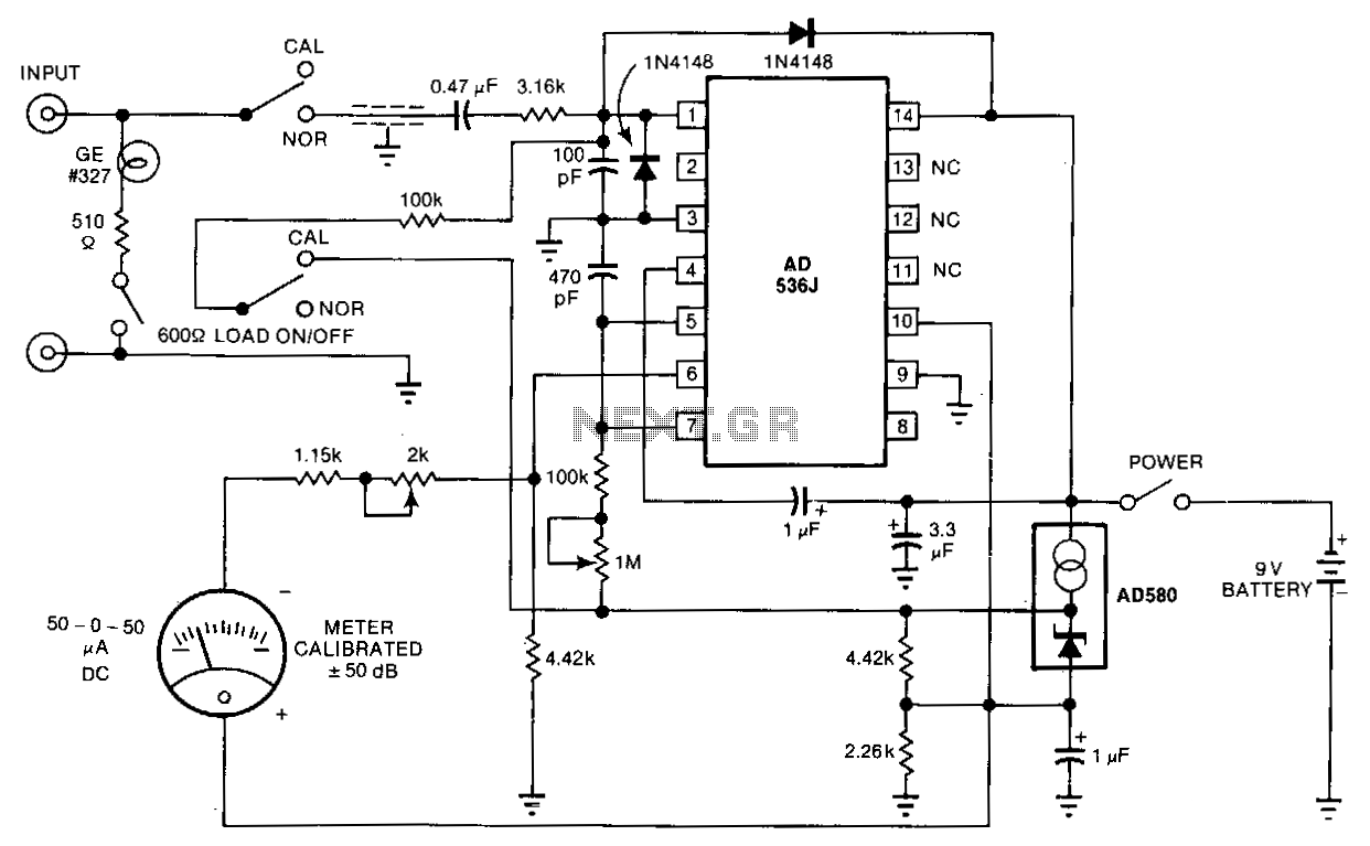
The telephone-line decibel meter and line-voltage sensor enables accurate monitoring and adjustment of telephone sound levels. The 600-ohm resistor appropriately terminates the line. The power consumption from the 9-volt battery is 2 mA, and the meter offers a ±30...
Warning: include(partials/cookie-banner.php): Failed to open stream: Permission denied in /var/www/html/nextgr/view-circuit.php on line 713
Warning: include(): Failed opening 'partials/cookie-banner.php' for inclusion (include_path='.:/usr/share/php') in /var/www/html/nextgr/view-circuit.php on line 713