
Sound Operated Flip Flop Based On The LM324 IC
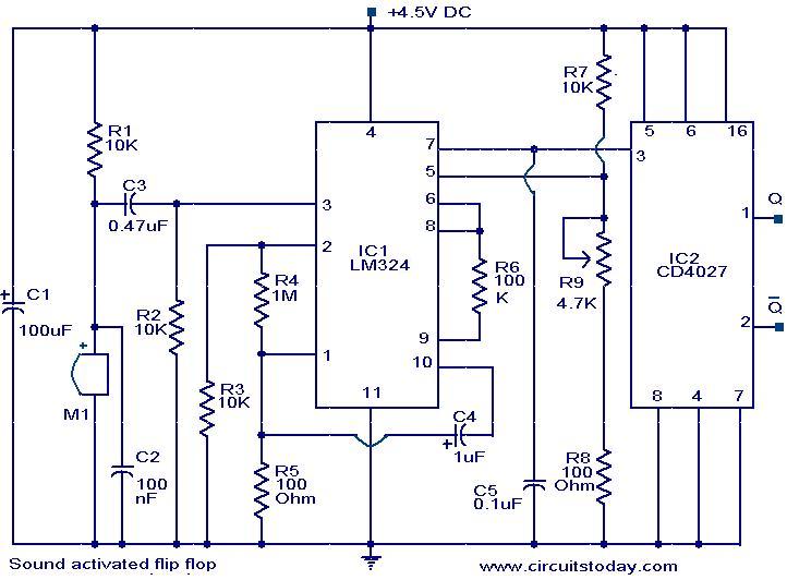
The Sound Operated Flip Flop circuit utilizes the LM324 operational amplifier, which consists of four independent, high-gain, frequency-compensated operational amplifiers. In this configuration, the circuit is designed to respond to audio signals captured by a condenser microphone. The microphone converts sound waves into an electrical signal, which is then amplified by the operational amplifier.
The circuit typically includes a threshold detection mechanism, which allows it to distinguish between ambient noise and significant sound events. When the sound level exceeds a predefined threshold, the output of the operational amplifier changes state, triggering the flip-flop. This flip-flop can be configured to control various outputs, such as LEDs or relays, providing a visual or functional response to the detected sound.
Power supply considerations for the LM324 IC should ensure that the voltage levels are appropriate for the operational amplifier's specifications, typically ranging from 3V to 32V. Additionally, bypass capacitors should be placed close to the power supply pins of the IC to minimize noise and stabilize the power supply.
Overall, this circuit is a practical application of sound detection and can be utilized in various projects, such as sound-activated switches, alarms, or interactive devices, enhancing user engagement through auditory stimuli.The following circuit shows about Sound Operated Flip Flop. This circuit based on the LM324 IC. Features: condenser microphone is used for picking .. 🔗 External reference
Related Circuits
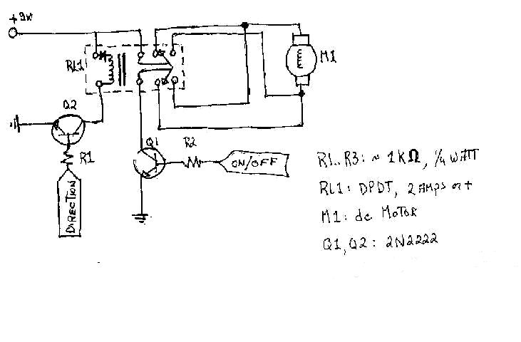
To create the circuitry described, a computer software capable of controlling a parallel port is required, with an estimated cost of approximately $30. For instance, a transistor (model number 2N2222) is priced around $0.50, while a DPDT relay costs...
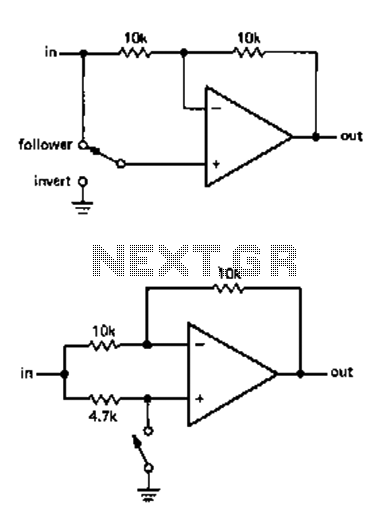
The circuit allows for the reversal or flipping of switch amplification without inversion. The voltage gain is dependent on the position of the switch, which can be either +1 or -1. There are two versions of the circuit, A...
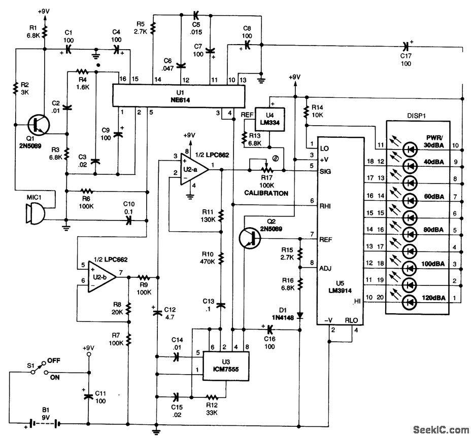
Power for the circuit is supplied by a 9-V battery (B1), providing a total current of 14.5 mA, which allows an alkaline battery to last approximately 250 hours. Audio signals are captured by the microphone (MIC1), and the output...

This project focuses on the design and development of a theft control system for automobiles, aimed at preventing and controlling vehicle theft. The system utilizes an embedded design based on GSM and GPS technology. It is installed within the...
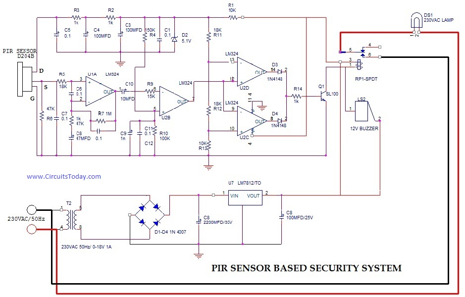
PIR (Passive Infrared Radial) Sensor-Based Security System, circuit diagram, working, applications. The PIR (Passive Infrared) sensor-based security system is designed to detect motion by measuring changes in infrared radiation emitted by objects in its vicinity, particularly warm bodies such as...
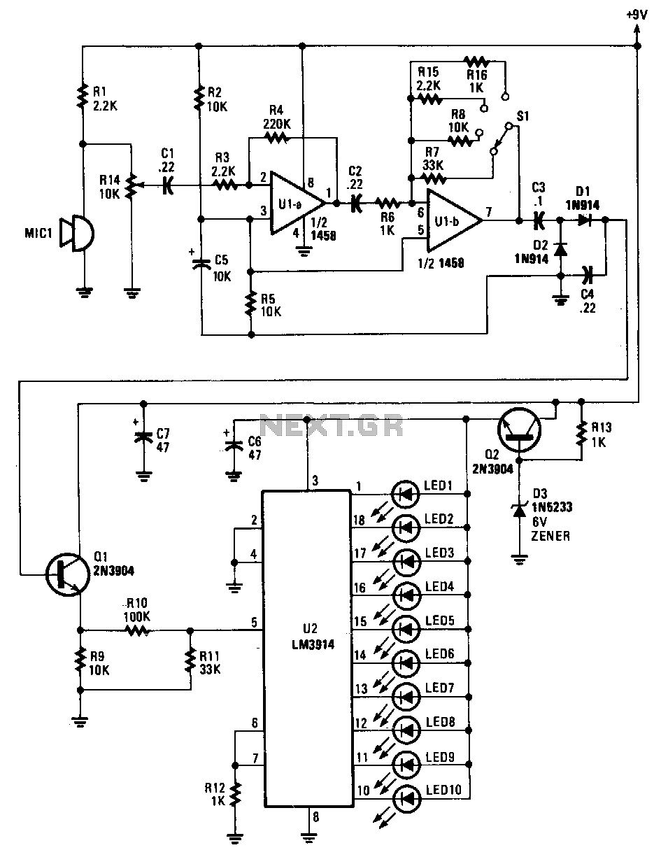
Sounds are captured by MIC1 and sent to the input of the first operational amplifier (op-amp). The signal is subsequently directed to the input of the second op-amp, U1B, where it is amplified by a factor ranging from 1...