
sound simple audio amplifier
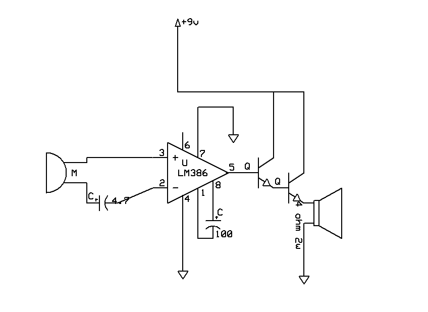
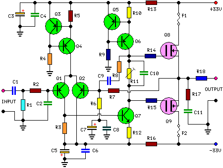
The circuit in question involves a sound amplification system utilizing two BC546 transistors, which are NPN bipolar junction transistors commonly used for low-power amplification. The primary objective of this circuit is to amplify the audio signal from a microphone or an audio input source, such as an MP3 player, to drive a speaker or headphone output.
The circuit typically includes a power supply, input coupling capacitors, biasing resistors, and output coupling capacitors. The audio input from the MP3 player should be connected through a coupling capacitor to block any DC component, ensuring that only the AC audio signal is passed to the base of the first transistor. The BC546 transistors are configured in a common emitter arrangement, which provides a good voltage gain.
To improve sound quality, several factors must be considered. First, the biasing resistors should be chosen to set the operating point of the transistors correctly, ensuring they are not in saturation or cutoff during operation. This can be achieved by using a voltage divider network at the base of the first transistor. Secondly, the coupling capacitors should be of adequate value to ensure low-frequency response is maintained while blocking DC.
Additionally, the choice of microphone is crucial. If a dynamic microphone is used, it may require additional pre-amplification due to its lower output level compared to condenser microphones. In this case, a dedicated preamplifier circuit may be necessary to boost the microphone signal before it reaches the BC546 transistors.
If the circuit has stopped functioning, it is essential to check for potential issues such as incorrect wiring, damaged components, or insufficient power supply voltage. Testing the transistors with a multimeter can help determine if they are operational. Furthermore, ensuring that all connections are secure and that there are no short circuits will aid in restoring functionality.
In summary, to enhance the sound quality and ensure reliable operation of the circuit, attention should be paid to the selection of components, proper biasing, and the overall configuration of the circuit.The quality sound was terrible, and suddenly it stoped working. Can anyone explain me in which part of the circuit i did something wrong any sugestions to improve the sound quality and make it work the transistors used are both BC546, and the microphone was acctually an input for an mp3 player, but i didn`t found in the programam that i did the schematics, so i put i microphone. 🔗 External reference
Related Circuits
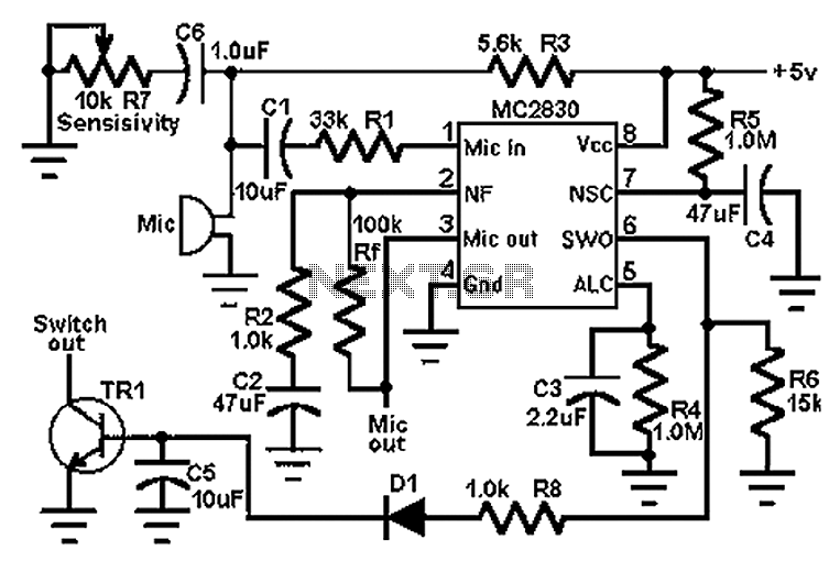
The circuit schematic utilizes the MC2830 voice circuit. Traditional voice circuits are unable to differentiate between speech and noise in the input signal. In noisy environments, such as those caused by switches, this limitation is significant. To address this...
This circuit is a small +5V power supply, which is useful when experimenting with digital electronics. Small inexpensive wall transformers with variable output voltage are available from any electronics shop and supermarket. Those transformers are easily available, but usually...
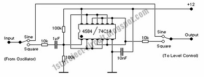
Prior to emailing Pablo Gian Villamil, he provided a link to his class notes on generating polyphonic sound with Arduino. Efforts were made to understand his circuitry through various blog posts and component listings, including the CMOS Hex Schmitt...
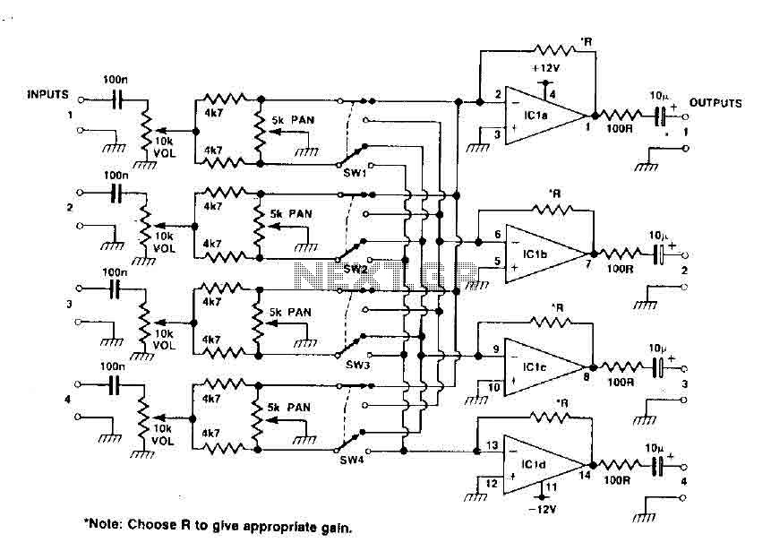
This circuit functions as a mixer for stereo tracks, utilizing a quad operational amplifier IC to provide gain for each track. The pan control allows for panning between two tracks when the switch is set to high, and when...
This circuit can be directly connected to CD players, tuners, and tape recorders. It requires the addition of a 10K logarithmic potentiometer (dual gang for stereo) and a switch to accommodate various sources. Proper grounding is crucial to eliminate...
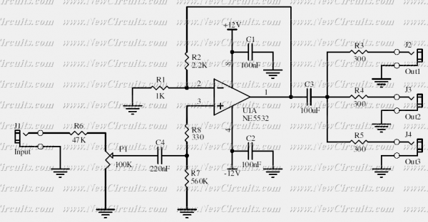
This circuit is suitable to amplify and distribute the audio signals. The input audio signal is applied to the J1 and after passing through the P1, it is buffered and amplified by the U1 prepared to redistribute. It has...
Warning: include(partials/cookie-banner.php): Failed to open stream: Permission denied in /var/www/html/nextgr/view-circuit.php on line 713
Warning: include(): Failed opening 'partials/cookie-banner.php' for inclusion (include_path='.:/usr/share/php') in /var/www/html/nextgr/view-circuit.php on line 713