
Spectrum Stalker
The Krohn-Hite 5100A VCO is essential for generating a controlled frequency output, which is vital in applications requiring precise frequency modulation. The design of the Spectrum Stalker box incorporates a dual waveform generator capable of producing both triangle and sawtooth waveforms, which are crucial for visual representation on the oscilloscope. The internal operational amplifiers are configured to ensure that the output signals are appropriately scaled and offset to align with the oscilloscope's requirements, facilitating accurate frequency measurements.
The implementation of the HI and LO-LIMIT controls allows for dynamic adjustments to the displayed frequency range, enabling users to focus on specific areas of interest within the broader frequency spectrum. The ability to sweep from low to moderate frequencies is particularly beneficial for observing the resonance characteristics of various coil configurations. The interaction between the primary and secondary coils in the Tesla Coil setup is critical; as the secondary coil is adjusted, the resulting changes in coupling will directly influence the observed resonance behavior.
The observed resonance blooms provide valuable information regarding the coupling efficiency between the coils. The distinction between under-coupled and over-coupled states is highlighted in the resonance profile, offering insights into the tuning process. The methodology employed in this setup not only enables practical experimentation but also serves as a foundation for further exploration into resonant phenomena in electromagnetic systems.
In summary, the integration of the Krohn-Hite 5100A VCO with the Spectrum Stalker waveform generator and oscilloscope presents a comprehensive approach to studying frequency response characteristics in Tesla Coil systems. The careful calibration and adjustment of the circuit parameters will facilitate a deeper understanding of resonance behaviors and their implications in electronic engineering applications.For one thing the Krohn-Hite 5100A VCO takes Zero to -17 VDC to drive the VCO output frequency. But the O-Scope X-axis wants 0 to +5. 7 volts to have the X-axis represent increasing frequency to the right. So, the O-Scope frame had to float to get -Volts into the KH 5100A and use same signal to get +Volts into the O-scope. Too confusing for a quick ie hookup. To facilitate easier setup, the above Spectrum Stalker box is under construction. This box will create 0 to +5. 7 VDC triangle and saw tooth voltage waveforms to drive the O-Scope X-axis. Internal Op-amps provide offset and gain to make the O-Scope X-axis Grid calibrated in frequency. In addition, the sweep range can be bracketed via HI & LO-LIMIT front panel knobs to display any portion of the frequency range. The KH Model 5100A Generator VCO has a response that may be in the 10`s of Hertz range so too high a VCO slew rate will cause the resonance bloom to shift from the correct frequency (x-position) on the O-Scope CRT.
The Spectrum Stalker internal oscillator will sweep the O-Scope x-axis from a couple Hz to about 30 Hz. In the triangle mode, the resonance bloom will be seen with advancing and declining VCO drive volts. If the VCO output frequency is not tracking fast enough, the spectrum `bloom` will be seen to shift left and right.
The higher the scan rate, the more the shift. The HI-LIMIT and LO_LIMIT knobs will permit bracketing the `resonance bloom` to increase repetitive scan rate while using slower VCO slew rate. This trick can minimize phase shift of the apparent resonance position for increasing versus decreasing VCO frequency.
Saw-tooth waveform will also cause shift of the apparent spectrum, but just in one direction which makes a better picture. May have to do a O-Scope Z-axis blanking during sawtooth retrace. Now the experimenter is free to move the TC secondary coil up and down, changing the degree of coupling between the primary and secondary, and compare the performance of the Tesla Coil versus coupling.
The Cartoon shows (absolute value of) the general shape of the `resonance bloom` that will occur for P-S coil pairs that are under-coupled to over coupled. The ideal coupling should be the `C` trace, slightly over coupled to broaden the resonance bandwidth.
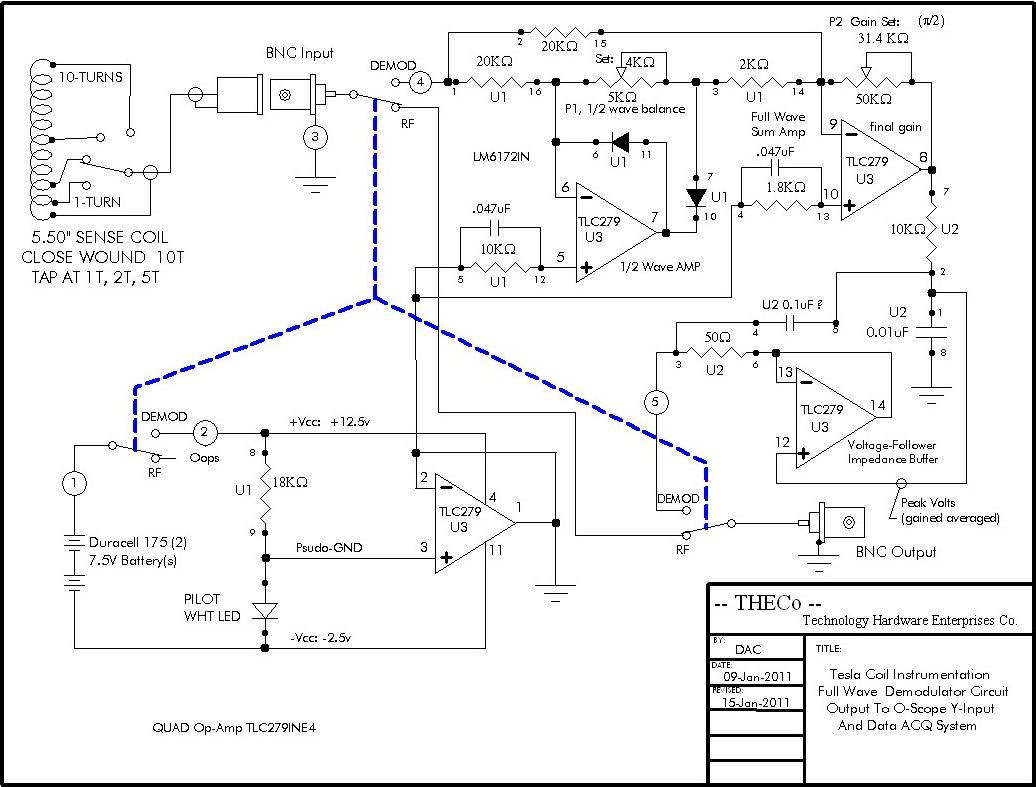
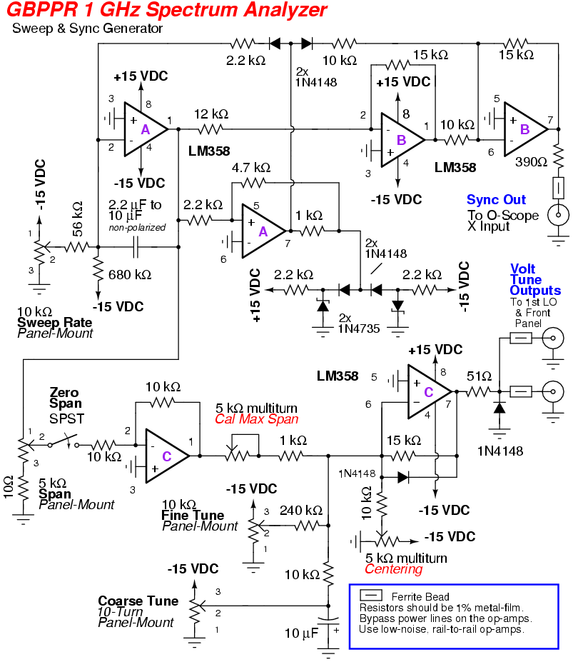
This is fascinating stuff; trust me. The schematic is shown below. Notice the `05 date, shows how far behind this project is. After wire and debug, circuit updates will be posted. BELOW: Spectrum Stalker Circuit card stuffed with chips plus component boards, ready for smoke test. Front panel wiring is last item before power up and debug. The triple output (+8, -8 and -18 vdc) power supply for CMOS circuitry with jumper to the circuit board is wired and tested. The circuit card (with DIP wire markers) and front panel are ready for wiring. Updated schematic with chip and component U-numbers (U1-U8) shown below. Should have the circuit wired in a couple days, maybe a day for trouble shoot and test. Then it is coil coupling measurement time! The Spectrum Stalker is working, day & 1/2 debug; couple minor circuit changes (later on that, Rev-C).
The base of the coil is grounded. The left picture above shows 3 resonance blooms. The 1st bloom to the left is the fundamental -wave 340 kHz resonance spike. The second (taller) spike is end-to-center resonance that places the HV peak near the center of the coil (and the coil ends are both voltage nodes). This test was performed with an un-tuned primary driver coil excited by the Krohn-Hite VCO output. The coils as pictured looks under coupled (sharp spike), but I am not sure about that as yet; untuned-tuned may not ever show the overcoupled sidebands.
I will investigate the behavior (bloom shape) for untuned-tuned at various coil coupling (just to see). We all may be learning some physicsstuff during upcoming resonance exercises and tests. Of course, the classical tuned-tuned over coupling side-bands w 🔗 External reference
Related Circuits
This 3 channel 15 LED spectrum analyzer is the perfect addition to any audio amp project. It produces fantastic displays on three LED bars that can be individually adjusted for any particular frequency range. The circuit will take line...
The external audio spectrum display circuit is designed for high-end audio equipment, providing both real-time playback signal analysis and visually appealing effects. This display does not require any electrical connections to the sound equipment; it can simply be placed...
The circuit shown in Figure 1 uses only two ICs, and has a bandwidth that is adjustable from more than one octave down to a tenth of an octave. As shown, the frequency range is 20 Hz. to 20...

To invoke the Spectrum +3 diagnostic routines, first reset the machine while holding the BREAK key down. This will bring up the test card display. Next, hold down the QAZMLP keys for a few seconds until the diagnostic title...
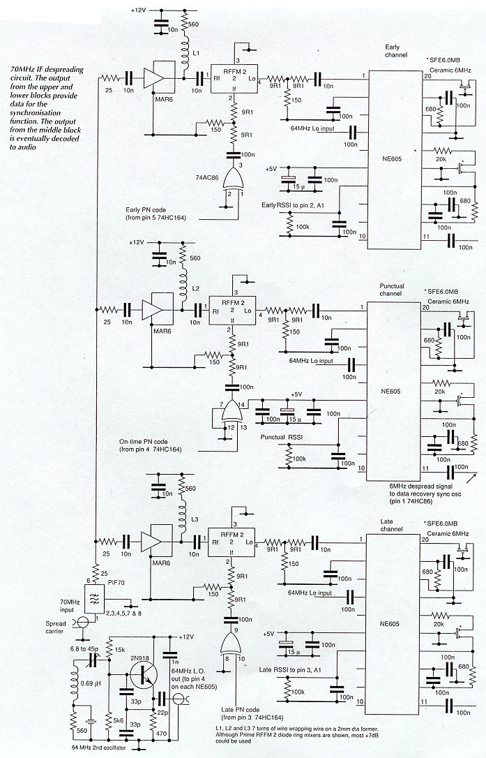
Until recently, spread spectrum techniques were primarily utilized in military applications. Their implementation in GPS and modern cellular phones is paving the way for various civil applications. This article, the first of two parts, explores the technology by detailing...
An RF spectrum analyzer is an essential tool for experimenters. The spectrum analyzer project described here is an enhancement of the "Spectrum Analyzer for the Radio Amateur" (Part 2) project by Wes Hayward (W7ZOI) and Terry White (K7TAU), which...