
Speed-controlled-reversible-dc-motor-drive
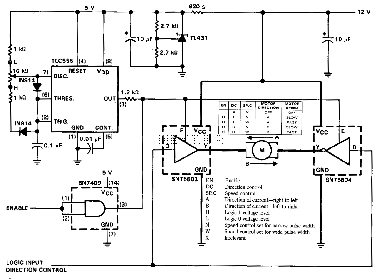
The figure illustrates a reversible DC motor drive application with adjustable speed control. The D inputs for these drivers are complementary and can be tied together and driven from the same logic control for bidirectional motor drive. The enables are tied together and driven by a pulse-width-modulated generator providing on-duty cycles of 10% to 90% for speed control. A separate enable control is provided through an SN7409 logic gate. More: See the truth table for this motor controller application. Definitions for the terms used in the truth table are as follows: -EN Enable -DC Direction control -SP.C Speed control -A Direction of current - right to left -B Direction of current - left to right -H Logic 1 voltage level -L Logic 0 voltage level -N Speed control set for narrow pulse width -W Speed control set for wide pulse width -X Irrelevant.
The described circuit functions as a reversible DC motor drive system, enabling precise control over motor direction and speed. The D inputs, being complementary, allow for a straightforward configuration where they can be interconnected to facilitate bidirectional operation. This means that a single control logic can manage the direction of the motor by altering the state of these inputs.
The pulse-width modulation (PWM) generator plays a crucial role in speed regulation, providing a range of duty cycles from 10% to 90%. This variation allows for fine-tuning of the motor's speed, making it adaptable to different operational requirements. The PWM signal modulates the average power delivered to the motor, effectively controlling its speed without the need for complex analog components.
The use of the SN7409 logic gate for separate enable control adds an additional layer of flexibility to the system. This gate can be used to manage the overall activation of the motor driver circuit, ensuring that the motor is only powered when necessary. This feature is particularly useful for applications requiring energy efficiency or safety measures.
The truth table associated with this motor controller application provides a clear overview of the operational states based on the logic inputs. Each term defined in the truth table, such as EN, DC, and SP.C, indicates essential control parameters that dictate the motor's functionality. The definitions of current direction (A and B) clarify how the motor will respond to the control signals, while the logic levels (H and L) establish the operational thresholds for the inputs. The specifications for narrow and wide pulse widths (N and W) further refine the speed control capabilities, allowing users to select the appropriate response based on the application’s demands.
In summary, this reversible DC motor drive application offers a robust solution for controlling motor speed and direction through a combination of complementary inputs, PWM for speed modulation, and logic gates for enable control, making it suitable for a wide range of electronic applications.The figure illustrates a reversible de motor drive application with adjustable speed control. The D inputs for these drivers are complementary and can be tied together and driven from the same logic control for bidirectional motor drive. The enables are tied together and driven by a pulse-width-modulated generator providing on duty cycles of 10 to 90% for speed control.
A separate enable control is provided through an SN7409 logic gate. See the truth table for this motor controller application. Definitions for the terms used in the truth table are as follows: -EN Enable -DC Direction control -SP.C Speed control -A Direction of current-right to left -B Direction of current-left to right -H Logic 1 voltage level -L Logic 0 voltage level -N Speed control setJor narrow pulse width -w Speed control set for wide pulse width -X Irrelevant 🔗 External reference