
Speed of Light with Nanosecond Pulsed 650 nm Diode Laser
The described circuit utilizes a time-of-flight measurement technique to ascertain the speed of light by employing a pulsed laser and advanced detection methods. The laser diode, selected for its low output power and ability to be modulated, is driven by an avalanche transistor configured to generate short electrical pulses. The choice of the 2N2369 transistor is crucial, as it allows for avalanche breakdown, enabling the generation of high-frequency pulses necessary for precise measurements. The circuit design emphasizes minimizing parasitic inductance and capacitance to maintain the integrity of the pulse shape, which is vital for accurate time delay measurements.
The setup includes a beam splitter that directs the laser light along two paths, one of which is delayed by a known distance. The reflected signals are captured by a high-speed Si pin detector, which converts the optical signals back into electrical signals for analysis. The oscilloscope is used to visualize the time delay between the two signals, allowing for the calculation of the speed of light based on the known distance and the measured time delay.
In practice, careful attention should be given to the layout of the components to ensure minimal interference and signal degradation. Short connections, proper grounding, and the use of high-quality components will enhance the reliability and accuracy of the measurements. This circuit not only serves the purpose of measuring the speed of light but can also be adapted for various applications in optical communications and high-speed signal processing, showcasing its versatility in the field of electronics.The speed of light has been measured many different ways using many ingenious methods. The following note describes a method which is conceptually very easy to understand and fairly easy to implement. The technique is the simple time-of-flight optical pulse delay method using a fairly short (nanosecond) optical pulse and an oscilloscope with bandw
idth between 50 - 100 MHz. Common low power laser pointers, typically emit at a wavelength of 650 nm and operate from two to four 1. 5 V button cells. Many of these lasers can be easily extracted from the pointer assembly and pulse-modulated to several hundred megahertz.
The laser used here was removed from a low power (< 5mW) laser pointer assembly from a popular retail outlet. The laser is prebiased below threshold, at 5 - 10 mA current (threshold current for the laser used here is 24 mA) using an inductor as a bias insertion element.
A short (< 5 ns) electrical pulse modulates the laser. Since a very low duty cycle is used for pulsing the laser, fairly high current pulses are possible without degrading the laser. The actual forward current and voltage achieved during the drive pulse are dependent on the details of the I-V characteristic of the specific laser used, but are typically in the range of 50 - 100 mA and 6 - 10 V respectively.
The short electrical pulse is generated using a simple avalanche transistor circuit. Due to the high frequency content of the short pulse, the actual shape of the current pulse driving the laser will depend on the circuit components (series resistors etc. ) and parasitic electrical effects (series inductance of connection wires etc. ) The circuit has been described by Jim Williams in a Linear Technology Measurement and Control Circuit Collection and has many other uses.
A suitable choice for the avalanche transistor is the 2N2369 NPN switching transistor, available at low cost from Electronix Express. The optical pulse delay between the signal reflected from a beam-splitter close to the laser and the path-delayed signal (time delay determined by mirror distances) is measured using a high-speed Si pin detector (ThorLabs PDA 10A 150 MHz BW).
In this setup, a 100 MHz oscilloscope was used to resolve the time delay of the two signals. Sufficiently high-speed Si pin detectors are readily available from many different suppliers at low cost. The overall setup showing mirrors, laser, drive circuit and detection circuit. The pulse delay measured corresponds to the optical path delay between the two paths: Closeup of the avalanche transistor driver circuit, laser diode (at top) with bias (left) and pulse (right) connections.
This setup, used to quickly evaluate different diodes and circuit elements, should be properly packaged with good rf-design (short leads, good ground connections etc. ). However, the requirements for measuring the speed of light do not require excessive attention to final circuit implementation.
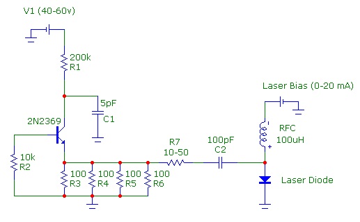
Schematic diagram of avalanche-pulse generation circuit and laser-diode connection. With these typical values, a pulse width of 500ps - 1ns is achieveable. The pulse width is determined by the collector capacitor C1 and the total emitter load resistance (typically 10 - 20 ohm). C1 should be kept below 15 pF to achieve short pulses. The transistor must be one exhibiting avalanche breakdown behaviour such as the 2N2369. The transistor power supply V1 should be adjusted until avalanching just starts (typically around 50 V for the 2N2369).
(Some basic suggestions on simple power supply possibilities are given below). The pulse repetition rate is determined by the RC time constant of the collector resistor R1 and C1. R1 generally can be any value from 200 kohm to 1 Mohm. The four emitter resistors in parallel (R3-R6) reduce parasitic inductance. R7 should be adjusted to limit the current provided to the laser during the pulse. All components C1, C2, R2-R7 should be soldered as close togethe 🔗 External reference
Related Circuits
The circuit utilizes a 555 timer integrated circuit (IC) configured as an astable multivibrator. The flashing rate can be adjusted from very fast to a maximum of once every 1.5 seconds by changing the setting of the preset variable...
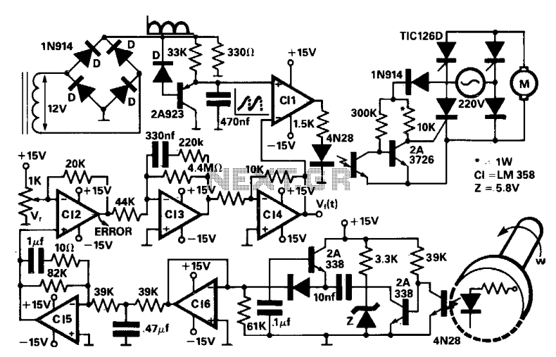
A four thyristor controlled bridge is utilized for operation in two quadrants of the torque-speed characteristics. In the trigger circuits, conventional pulse transformers are substituted with self-biased circuits, which reduce gate power consumption and enhance noise immunity. Electrical isolation...
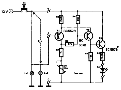
The circuit described below monitors the car's brake lights and indicates their operational status using a 12V light-emitting diode (LED). This functionality can prevent fines for driving with defective brake lights and enhance road safety. The monitor relies on...
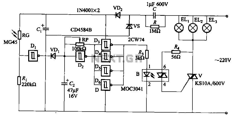
The circuit utilizes a CD4584B six Schmitt trigger integrated circuit (IC) with components Di and Ri forming a photometric circuit. D2, along with RP and C2, comprises an adjustable frequency ultra-low frequency oscillation device, where RP serves as an...
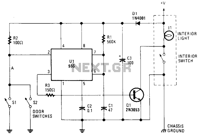
The circuit maintains the courtesy light's illumination for 30 seconds after the door is closed. The lead from the door switch is disconnected and linked to the 555 timer circuit. The 555 timer is configured in monostable mode and...
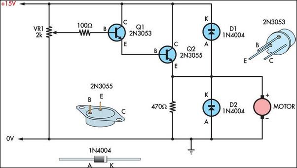
Two simple 12V DC motor speed controllers can be constructed for a minimal cost. These controllers take advantage of the principle that the rotational speed of a DC motor... DC motor speed controllers are essential components in various applications where...
Warning: include(partials/cookie-banner.php): Failed to open stream: Permission denied in /var/www/html/nextgr/view-circuit.php on line 713
Warning: include(): Failed opening 'partials/cookie-banner.php' for inclusion (include_path='.:/usr/share/php') in /var/www/html/nextgr/view-circuit.php on line 713