
Square wave generator III
The circuit operates by utilizing a stable RC oscillator configuration, which is essential for generating precise square waveforms necessary for testing television monitor amplifiers. The choice of NAND gates (IC4-4011) provides a reliable method of oscillation, with the RC time constant determining the frequency of oscillation. The use of bilateral switches (IC2, IC3-4016) allows for dynamic alteration of the capacitor value, thereby enabling the circuit to produce various frequencies as required for different testing conditions.
The counter/decoder (IC1-4017) plays a critical role in controlling the timing of the waveform generation. It receives clock pulses, which are generated from a stable clock source, and outputs signals that drive the bilateral switches. The synchronization of these outputs with vertical blanking pulses ensures that the waveform generation is coherent with the television signal, facilitating accurate characterization of the monitor's response.
Horizontal synchronization is achieved through the application of composite blanking pulses, which are negative in polarity. This technique ensures that the generated waveforms align with the horizontal synchronization requirements of the television system, thereby preventing any potential distortion during the testing phase.
The frequency steps provided by the oscillator (460 kHz to 3600 kHz) are crucial for evaluating the frequency response of television monitor amplifiers across a range of operational conditions. Each frequency corresponds to a specific test scenario, allowing engineers to assess the performance of the monitor at various signal frequencies.
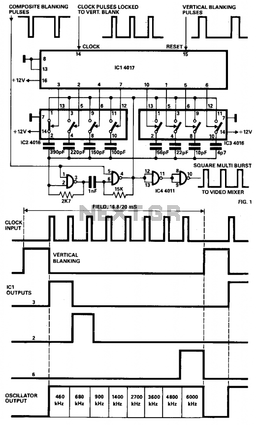
Finally, the mixer stage is essential for combining the generated video signal with the composite sync signal. This integration is vital for producing a composite video output that can be utilized for further testing or analysis, ensuring that the generated signals are compatible with standard television input requirements. Overall, this circuit serves as a valuable tool for engineers and technicians in the field of television technology, providing a versatile means of testing and characterizing monitor performance.The generator described here is intended for multiburst signal square waveform generation and can be used as a device for characterizing the response of TV monitor amplifiers as shown. The circuit is an RC oscillator with NAND gates (IC4-4011), with its capacitor C changed periodically by means of bilateral switches (IC2, IC3-4016).
The control inputs of bilateral switches are driven by the outputs of a counter/decoder (IC1-4017) the operation of which is determined by generated clock pulses, so that they occur eight times at half-picture (field). These pulses are locked to vertical blank pulses. Horizontal synchronization is achieved by means of composite blanking pulses (negative polarization) applied to pins 1 and 5 of IC4. The oscillator frequency changes in the following discrete steps: 460 kHz, 680 kHz, 900 kHz, 1400 kHz, 2700 kHz, 3600 kHz, for the time of one frame.
The video signal is fed on a mixer where it is superimposed with a composite sync signal. 🔗 External reference
Related Circuits
This is a kHz sine wave generator circuit built based on the configuration of an inverted Wien bridge (see C1-R3 C2-R4). R5 and R7 are used for output amplitude setting. Set R5 to read 1V RMS on an audio...
This circuit is designed to generate high-quality square waves by converting a sine wave obtained from an existing generator. A key feature of this circuit is that it does not require an external power source; it can be directly...
This circuit generates sine wave oscillations, but it can also be modified to produce triangle or square wave functions. The frequency is adjustable by varying the current. By disconnecting the 20k resistor (RIN) from the reference (REF) pin (pin...
This type of design can produce a very high amperage current for a fraction of a second that can be used to do some useful work if properly harnessed. The switching device could be a rotating spark gap as...
This schematic is simple and easy to construct. The integrated circuit (IC) generates all the sound effects, with the output at Pin 3 being amplified by a transistor. A 64-ohm loudspeaker can be used instead of the 56-ohm resistor...
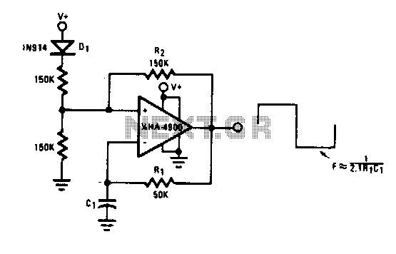
This self-starting fixed frequency oscillator circuit provides excellent frequency stability. R1 and C1 form the frequency-determining network, while R2 supplies regenerative feedback. Diode D1 improves stability by compensating for the difference between Voh and Vsupply. In applications requiring a...