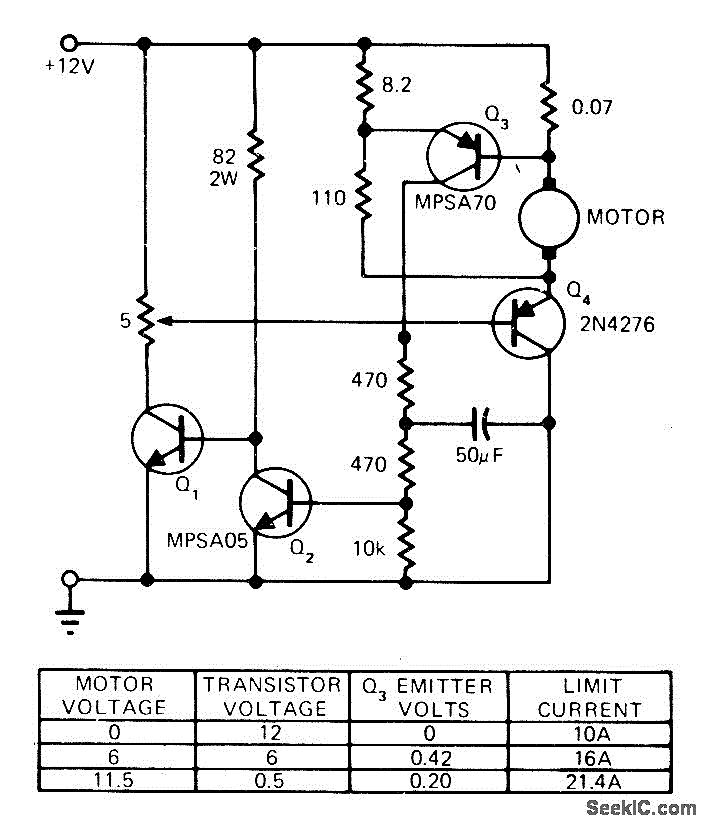
STALLED_MOTOR_PROTECTION

The modification of a basic speed control circuit for small DC permanent-magnet motors implements a maximum current limit during normal operating conditions and a reduced current limit during stall conditions. This design aims to limit the dissipation of series transistor Q4 to a safe value. When the motor stalls, the motor voltage decreases, which in turn reduces the voltage and current necessary to activate transistor Q3.
The modified speed control circuit integrates several key components to ensure efficient operation and protection of the motor and associated circuitry. The circuit typically consists of a power supply, a motor driver (which includes the series transistor Q4), and control transistors (such as Q3).
In normal operation, the circuit allows for full voltage to be supplied to the motor, enabling it to reach its designed speed. However, to prevent damage to the transistor Q4 during high current situations, a current sensing mechanism is employed. This may involve a shunt resistor placed in series with the motor, allowing the circuit to monitor the current flowing through the motor.
When the motor experiences a stall condition, the voltage drop across the motor causes the current to also decrease. This reduction is detected by the control circuitry, which adjusts the base drive of Q3. By limiting the current flowing through Q4 during stalling, the circuit effectively protects the transistor from overheating and potential failure.
Additional features may include feedback mechanisms to adjust the duty cycle of the PWM signal controlling Q4, further enhancing the circuit's responsiveness to changing load conditions. The design ensures that the motor operates efficiently while maintaining the integrity of the components involved, particularly under varying operational scenarios.
Overall, this modified speed control circuit is crucial for applications requiring reliable performance from small DC permanent-magnet motors, providing both operational efficiency and component protection.Modification of basic speed control circuit for small DC permanent-magnet motors provides maximum current limit under normal conditions and reduced current limit under stall conditions, to limit dissipation of series transistor Q4, to safe value. When motor stalls, motor voltage falls, reducing voltage and motor current required to turn on Q3 and thereby l..
🔗 External reference
Warning: include(partials/cookie-banner.php): Failed to open stream: Permission denied in /var/www/html/nextgr/view-circuit.php on line 713
Warning: include(): Failed opening 'partials/cookie-banner.php' for inclusion (include_path='.:/usr/share/php') in /var/www/html/nextgr/view-circuit.php on line 713