
State-variable-active-filter
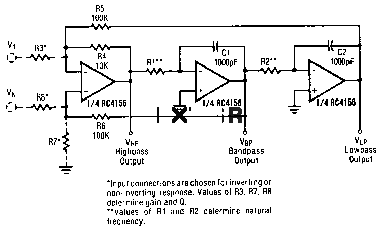
A generalized circuit diagram of the two-pole state-variable active filter is presented. This state-variable filter can be configured as either inverting or non-inverting and is capable of providing three simultaneous outputs: low-pass, bandpass, and high-pass. By incorporating an additional summing operational amplifier, a notch filter can also be achieved. Within the state-variable filter circuit, one amplifier is designated to perform the summing function, while the other two amplifiers serve as integrators. The selection of passive component values is arbitrary but must align with the operating range of the amplifier and the characteristics of the input signal. The values indicated for capacitors C1, C2 and resistors R4, R5, and R6 are arbitrary; however, preselecting these values can facilitate the filter tuning process, though alternative values may be employed if necessary.
The two-pole state-variable active filter is a versatile circuit that provides multiple filtering options in a single configuration. It utilizes operational amplifiers (op-amps) to create a flexible filter topology that can be adjusted to meet specific signal processing requirements. The design typically consists of two integrators and a summing amplifier, which work in conjunction to produce the desired output types.
In this circuit, the low-pass output allows low-frequency signals to pass while attenuating higher frequencies, making it suitable for applications requiring signal smoothing. The bandpass output permits a specific range of frequencies to pass through while blocking frequencies outside this range, ideal for applications in communications and audio processing. The high-pass output, conversely, allows high-frequency signals to pass while attenuating lower frequencies, which can be useful in applications where high-frequency signals are of primary interest.
The addition of a notch filter capability enhances the versatility of the design, enabling the attenuation of a specific frequency while maintaining the integrity of surrounding frequencies. This feature is particularly valuable in applications where interference at a specific frequency needs to be minimized.
The choice of passive components—resistors and capacitors—affects the filter's performance characteristics, such as cutoff frequency and quality factor. While the values of C1, C2, R4, R5, and R6 can be chosen arbitrarily, they should be selected based on the desired filter specifications and the operational limits of the op-amps used. The design allows for flexibility in tuning, which is critical for achieving optimal performance in various applications. It is essential to ensure that the selected component values are consistent with the input signal characteristics to avoid distortion and ensure accurate filtering.
Overall, the two-pole state-variable active filter represents a robust solution for implementing complex filtering requirements in electronic circuits, offering both flexibility and precision in signal processing tasks.A generalized circuit diagram of the two-pole state-variable active filter is shown. The state-variable filter can be inverting or noninverting and can simultaneously provide three outputs: low-pass, bandpass, and high-pass. A notch filter can be realized by adding one summing op amp. In the state-variable filter circuit, one amplifier performs a summing function and the other two act as integrators.
The choice of passive component values is arbitrary, but must be consistent with the amplifier operating range and input signal characteristics. The values shown for Cl, C2, R4, R5, and R6 are arbitrary. Preselecting their values will simplify the filter tuning procedures, but other values can be used if necessary.
🔗 External reference