
Steady flow of power transistor circuit
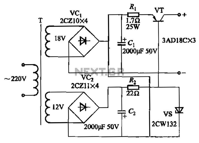
This circuit exemplifies a power supply regulation system designed to ensure a stable output current despite variations in input voltage or load conditions. The primary function is to maintain a constant current output, which is crucial for applications requiring precise power delivery.
The operation of the circuit can be achieved through various methods, including the use of feedback control mechanisms, which continuously monitor the output current and adjust the input parameters accordingly. This feedback loop is essential for compensating for any fluctuations in the power supply or changes in the load, thereby ensuring that the output remains stable.
In the illustrated circuit, components such as operational amplifiers may be employed to compare the desired output current with the actual output. When discrepancies are detected, the circuit adjusts the control signal to modulate the power supply or the load, thereby minimizing any deviations from the set current level.
Additionally, the design may incorporate filtering capacitors to smooth out any transient responses and provide a more stable output. The use of inductors can also help in managing load changes, as they resist changes in current and can provide temporary energy storage during load variations.
The performance characteristics of the circuit indicate that when the load transitions from 0 to 2n, the output current remains relatively stable, with fluctuations contained within a 10% range. This level of performance is indicative of a well-designed regulation circuit, capable of handling real-world conditions effectively.
Overall, this circuit is particularly suitable for applications in sensitive electronic devices where maintaining a constant current is essential for optimal operation and reliability. Characterized by a steady flow of power when the power supply voltage fluctuations or load changes, to maintain a constant load current. The output current of the circuit shown in Figure 4A. When the load changes from 0 to 2n, current changes less than 10%.
Related Circuits
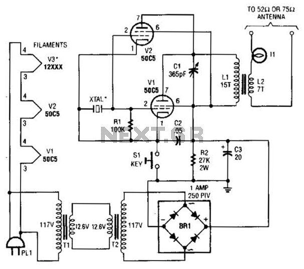
This low-power video transmitter is designed for remote control (R/C) applications, surveillance, or amateur radio purposes. It utilizes seven transistors within a crystal oscillator-multiplier RF power amplifier chain, along with a high-level video modulator. A supply voltage of 9...
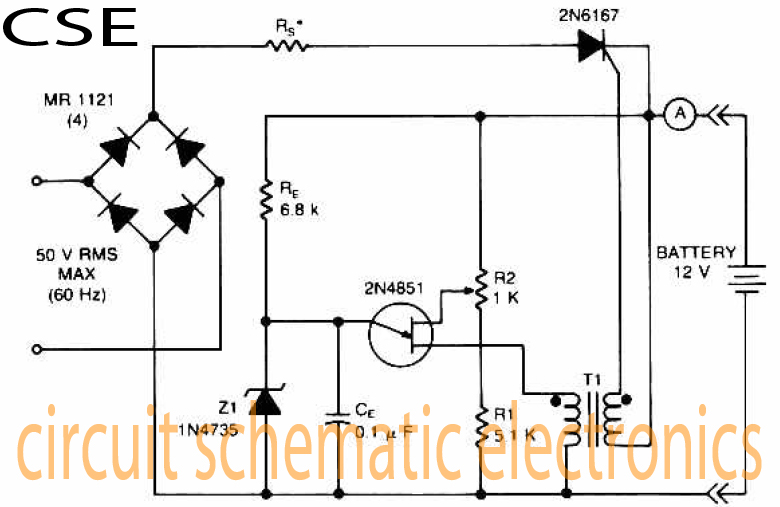
The accumulator charger circuit must provide a voltage that matches the specifications of the batteries being charged. For a 12-volt accumulator, the output voltage should not exceed 12 volts, nor should it fall significantly below this threshold. Failure to...
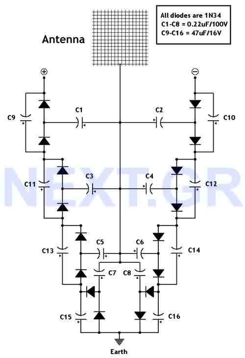
This circuit converts surrounding radio frequency waves to electric power. It can provide 40 Volts at 10 Watts indefinitely. The output power can be improved by adjusting the antenna. Placing the antenna near large metal objects increases power. The...
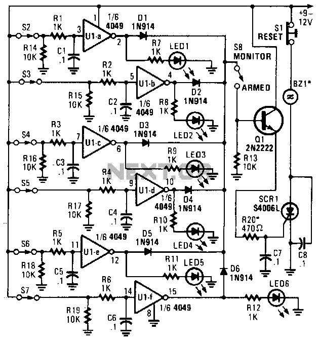
This alarm features status LEDs connected to each inverter output, which indicate the status of the corresponding sensor. S8 is utilized to monitor the switches through the LEDs or to activate an alarm using Q1 and SCR1. Additionally, BZ1...
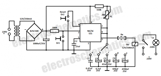
This time delay relay circuit is constructed using the NE/SE555 integrated circuit, manufactured by Intersil, which incorporates a precision timer. The circuit exhibits stability against temperature variations of 0.00. The NE/SE555 timer IC is a versatile device widely used in...
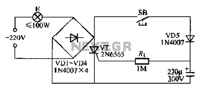
This circuit is a simple connection delay lamp circuit. When the lights are turned on and the switch is pressed, the power supply is activated. The capacitor charges rapidly, causing the thyristor (VT) to open, which in turn lights...