
stepper motor controller
The stepper motor controller circuit is designed to efficiently manage the operation of stepper motors across a range of specifications, making it versatile for various applications. The use of a 4017 decade counter allows for precise control of the stepper motor's stepping sequence, ensuring smooth operation. The implementation of TDA2030 audio amplifier ICs as comparators provides a cost-effective solution for driving the motor windings while maintaining the necessary current and voltage levels for optimal performance. This configuration is particularly beneficial for applications requiring precise control over motor positioning, such as robotics, CNC machines, and automated systems. The inclusion of safety features, such as short-circuit protection and over-temperature shutdown, enhances the reliability of the circuit in demanding environments. Furthermore, the ability to adjust the RPM and step size offers flexibility in motor performance, accommodating various operational requirements. Overall, this stepper motor controller circuit exemplifies an effective design for controlling stepper motors with a focus on functionality, safety, and adaptability.Stepper motors are available in several versions and sizes with a variety of operating voltages. The advantage of this general-purpose controller is that is can be used with a wide range of operating voltages, from approximately 5 V to 18 V. It can drive the motor with a peak voltage equal to half the supply voltage, so it can easily handle steppe
r motors designed for voltages between 2. 5 V and 9 V. The circuit can also supply motor currents up to 3. 5 A, which means it can be used to drive relatively large motors. The circuit is also short-circuit proof and has built-in over temperature protection. Two signals are required for driving a stepper motor. In logical terms, they constitute a Grey code, which means they are two square-wave signals with the same frequency but a constant phase difference of 90 degrees. IC1 generates a square-wave signal with a frequency that can be set using potentiometer P1. This frequency determines the rpm of the stepper motor. The Grey code is generated by a decimal counter in the form of a 4017. Outputs Q0 Q9 of the counter go high in succession in response to the rising edges of the clock signal.
The Grey code can be generated from the outputs by using two OR gates, which are formed here using two diodes and a resistor for each gate, to produce the I and Q signals. Here I` stands for in-phase` and Q` for quadrature`, which means it has a 90-degree phase offset from the I signal.
It is common practice to drive the windings of a stepper motor using a pair of push-pull circuits for each winding, which is called an H bridge`. That makes it possible to reverse the direction of the current through each winding, which is necessary for proper operation of a bipolar motor (one whose windings do not have centre taps).
Of course, it can also be used to properly drive a unipolar motor (with centre-tapped windings). Instead of using a push-pull circuit of this sort, here we decided to use audio amplifier ICs (type TDA2030), even though that may sound a bit strange. In functional terms, the TDA2030 is actually a sort of power opamp. It has a difference amplifier at the input and a push-pull driver stage at the output. IC3, IC4 and IC5 are all of this type (which is economically priced). Here IC3 and IC4 are wired as comparators. Their non-inverting inputs are driven by the previously mentioned I and Q signals, with the inverting inputs set to a potential equal to half the supply voltage.
That potential is supplied by the third TDA2030. The outputs of IC3 and IC4 thus track their non-inverting inputs, and each of them drives one motor winding. The other ends of the windings are in turn connected to half the supply voltage, provided by IC5. As one end of each winding is connected to a square-wave signal that alternates between 0 V and a potential close to the supply voltage, while the other end is at half the supply voltage, a voltage equal to half the supply voltage is always applied to each winding, but it alternates in polarity according to the states of the I and Q signals.
That`s exactly what we want for driving a bipolar stepper motor. The rpm can be varied using potentiometer P1, but the actual speed is different for each type of motor because it depends on the number of steps per revolution. The motor used in the prototype advanced by approximately 9 ° per step, and its speed could be adjusted over a range of approximately 2 to 10 seconds per revolution.
In principle, any desired speed can be obtained by adjusting the value of C1, as long as the motor can handle it. The adjustment range of P1 can be increased by reducing the value of resistor R5. The adjustment range is 1:(1000 + R5)/R5, where R5 is given in k. If a stepper motor is switched off by removing the supply voltage from the circuit, it`s possible for the motor to continue turning a certain amount due to its own inertia or the mechanical load on the motor (flywheel effect).
It`s also possible for the position of the motor to disagree with the states of the I and Q signals when power is first applied to the circuit. As a result, the motor can sometimes get confused` when starting up, with the result that it takes a step in the wrong direction before starting to move in direction defined by the drive signals.
These effects can be avoided by adding the optional switch S1 and a 1-k resistor, which can then be used to start and stop the motor. When S1 is closed, the clock signal stops but IC2 retains its output levels at that moment, so the continuous currents through the motor windings magnetically lock` the rotor in position.
The TDA2030 has internal over temperature protection, so the output current will be reduced automatically if the IC becomes too hot. For that reason, it is recommended to fit IC3, IC4 and IC5 to a heat sink (possibly a shared heat sink) when a relatively high-power motor is used.
The tab of the TO220 case is electrically bonded to the negative supply voltage pin, so the ICs can be attached to a shared heat sink without using insulating washers. 🔗 External reference
Related Circuits
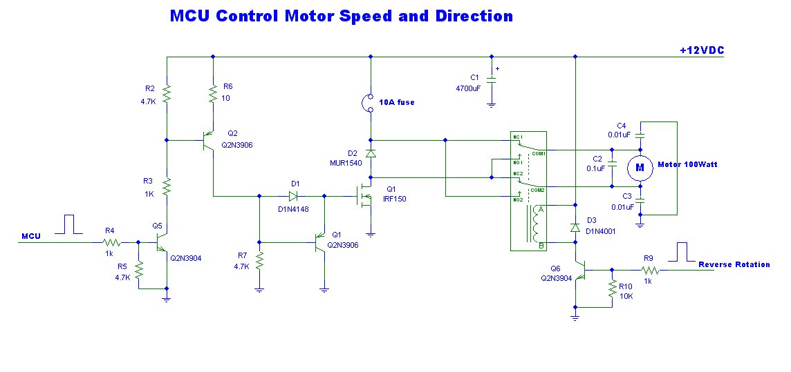
This is a power motor controller circuit designed for 12V applications. It utilizes a microcontroller unit (MCU) for signal control, operating at a high voltage level of approximately 3V. The circuit allows for the motor to be controlled to...
The HC-06 module is a slave mode serial Bluetooth data link manufactured by CSR. In this project, a mobile phone communicates with the AT89C2051 microcontroller via the HC-06 module. The complexity of the communication has been encapsulated within a...
The Intelligent Fan Controller regulates the speed of computer fans according to the internal temperature of the computer, minimizing noise levels. It utilizes a 4-wire, 2-wire, and 3-wire fan configuration in conjunction with a PIC microcontroller, specifically the PIC18F2550....
There are numerous applications for this hardware, including touch pads, proximity sensors, capacitive sensor readouts, high-precision capacitance measurements, ultra-small capacitance change detection, soil moisture sensing, and skin moisture measurement, among others. However, after searching for examples, it was surprising...
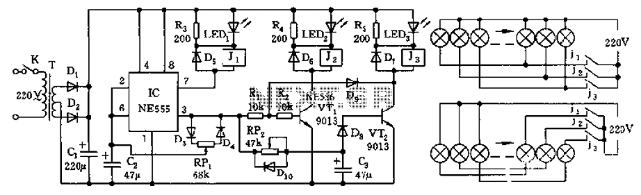
The controller features a buck rectifier circuit utilizing a 555 multivibrator, designed for controlling approximately 220V, 5W low-power parallel lights or 6 to 12V small bulb series. The 555 timer, along with components D3, D4, RP1, and C2, forms...
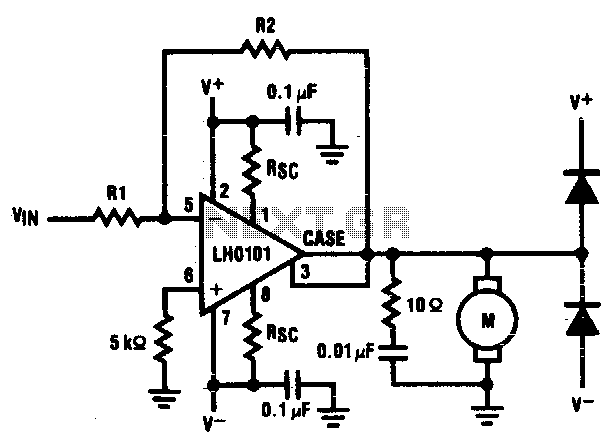
The motor driver amplifier is designed to deliver the rated current to the motor. It is important to manage power dissipation to remain within allowable limits. This precision speed regulation circuit utilizes rate feedback to maintain a constant motor...
Warning: include(partials/cookie-banner.php): Failed to open stream: Permission denied in /var/www/html/nextgr/view-circuit.php on line 713
Warning: include(): Failed opening 'partials/cookie-banner.php' for inclusion (include_path='.:/usr/share/php') in /var/www/html/nextgr/view-circuit.php on line 713