
Stepper Motor Controller
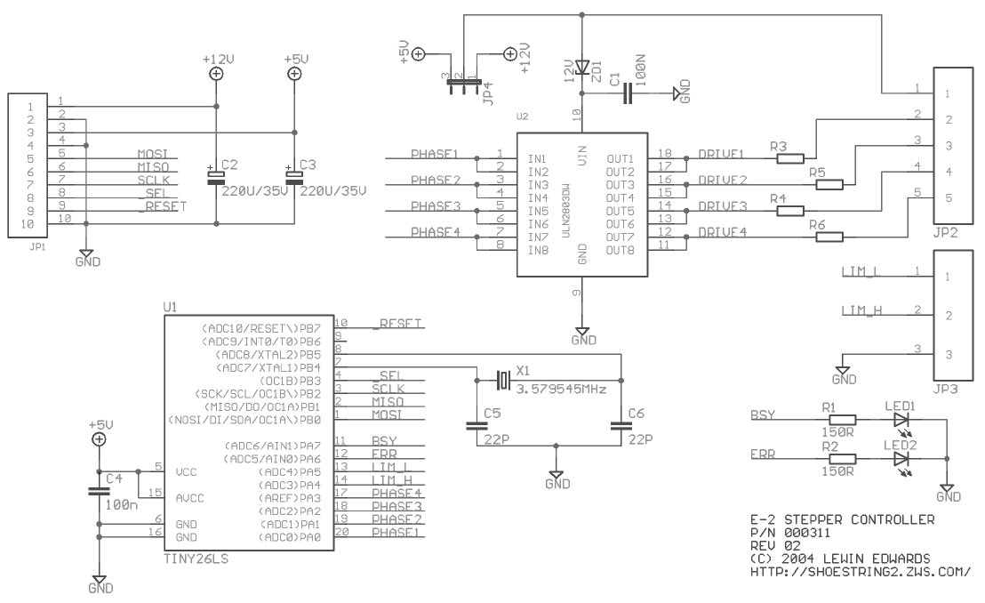
The stepper motor control circuit is designed to facilitate precise control over the motor's operation. The ULN2803 Darlington array serves as the interface between the microcontroller and the stepper motor coils, allowing for efficient switching of the coils with high voltage and current capacity. The microcontroller outputs control signals to the ULN2803, which in turn energizes the appropriate coils in sequence to achieve the desired stepping motion.
The use of limit switches enhances the functionality of the stepper motor system by providing a means to detect the physical boundaries of the motor's movement. When a limit switch is triggered, it sends a signal to the microcontroller, which can then halt the motor or reverse its direction, thereby preventing mechanical damage.
The choice of clock source is crucial for maintaining timing accuracy within the system. The NTSC colorburst crystal’s frequency ensures that the microcontroller operates within its optimal range, providing consistent timing for step pulses. This is particularly important for applications requiring precise positioning, as any timing discrepancies could result in positional errors.
The dual operational modes of the controller allow for flexibility in application. The drive mode is suitable for continuous operation, while the train mode is tailored for applications where precise positioning is paramount. By allowing the user to specify a target position, the system can autonomously navigate to that point, freeing up the user to manage other tasks concurrently.
Overall, the stepper motor control circuit offers a reliable and cost-effective solution for applications requiring precise motor control, with the added benefits of limit switch integration and dual operational modes for enhanced functionality.Stepper motors are useful for relatively low-speed, intermediate-torque drive and positioning applications, particularly where accurate sub-revolution rotor position control is necessary. Motors of this type are commonly used to drive the reels on electromechanical slot machines (one-armed bandits), to position floppy disk drive heads, operate trainable
camera platforms, and to power the drive wheels of small mobile robots. In times of yore, they were also used to position hard disk heads, though such applications have long ago been taken over by voice-coil type mechanisms. Stepper motors are simple and cheap to use, and you don`t need to have a fully closed-loop controller to use them accurately.
Servomotors are much faster, but for guaranteeable positioning accuracy, you need to have a position encoder on the shaft to provide feedback on the actuator`s position. By contrast, as long as you don`t stray outside your system`s nominal acceleration profile (see the following), a stepper-based system can reliably maintain its position indefinitely without recalibration.
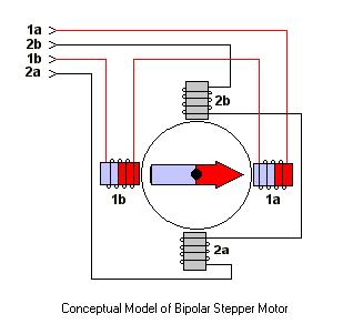
There are several types of stepper motors, with varying electrical drive requirements. However, by far the most common type of motor to be found on the surplus market (or scavenged from unwanted computer equipment) is the four-pole unipolar type14, so this is the type our circuit is designed to use. Without further ado, here`s the schematic15: This project uses the ULN2803 octal high-voltage, high-current Darlington array to switch the stepper coils.
This chip is readily available for around $0. 75 in small quantities, and it is a handy solution for driving moderate loads. Until recently, one could often find this chip, or its close relatives, in commercial stepper motor applications such as inkjet printers and both sheet-fed and flatbed scanners. At present, however, it appears to be in decline as application-specific microcontrollers with high-current drivers on-chip take over its market space.
On the subject of prices, you`ll notice that I`ve specified an NTSC colorburst crystal as the clock source, despite the fact that the tiny26L is rated at up to 8 MHz for a 5 V supply voltage. I chose the 3. 579545 MHz value, although it`s not a nice integer to work with, because these crystals are available everywhere and are often cheaper than other speeds.
Chances are you have several in your junkbox already, in fact. You`ll also find that application notes for microcontrollers almost always give precalculated example timing constant values (e. g. , for setting the baud rate of a UART) for this base clock speed. Our example stepper controller module also has two active-low limit switch inputs. These are optionally used to signal end-of-travel in the increment and decrement step directions. Note that JP4, which selects between 5 V or 12 V drive for the stepper coils, is intended to be a wire link for factory configuration, rather than a user-changeable jumper.
If you are using the device in 5 V drive mode, you should alter or remove ZD1; you can also omit C2, since it serves no function if you`re driving the motor off the +5 V rail. The controller operates in one of two modes: "drive" or "train. " In drive mode, you simply specify a speed and direction, and the motor turns in that direction until commanded to stop.
Optionally, you can request that it travel until either of the limit switches is triggered. Train mode is intended for positioning applications. In this mode, you command the stepper controller to seek to a specific offset from the current position, and it will automatically seek to that position while you carry out other tasks. The stepper will automatically cut off if it hits the high limi 🔗 External reference
Related Circuits
The circuit illustrated in Figure 3-178 is designed for controlling the speed and torque of a motor used in a continuous casting machine. It consists of the main circuit, a trigger circuit, and both manual and automatic control signal...
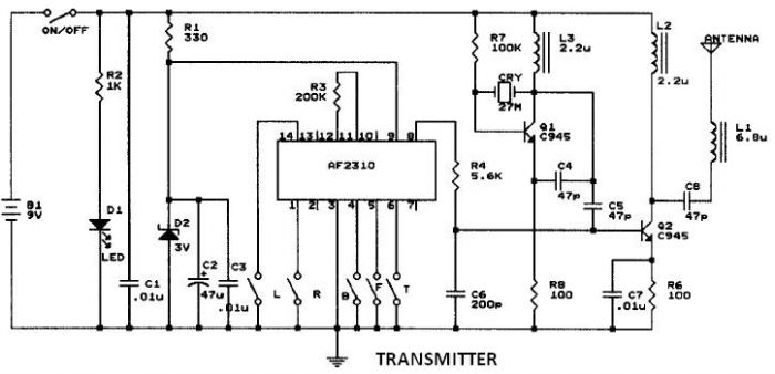
This circuit resembles that of a car radio-controlled toy with seven control functions: forward, forward-left, forward-right, backward, backward-left, backward-right, and stop. Additionally, this radio frequency circuit can be utilized for other electronic circuits that require a simple wireless motor...
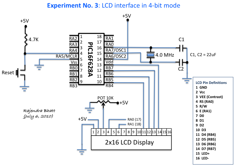
An HD44780 Character LCD is a liquid crystal display (LCD) device designed for interfacing with embedded systems. These screens are available in various configurations, including 8x1 (one row of eight characters), 16x2, and 20x4. The most commonly produced configuration...
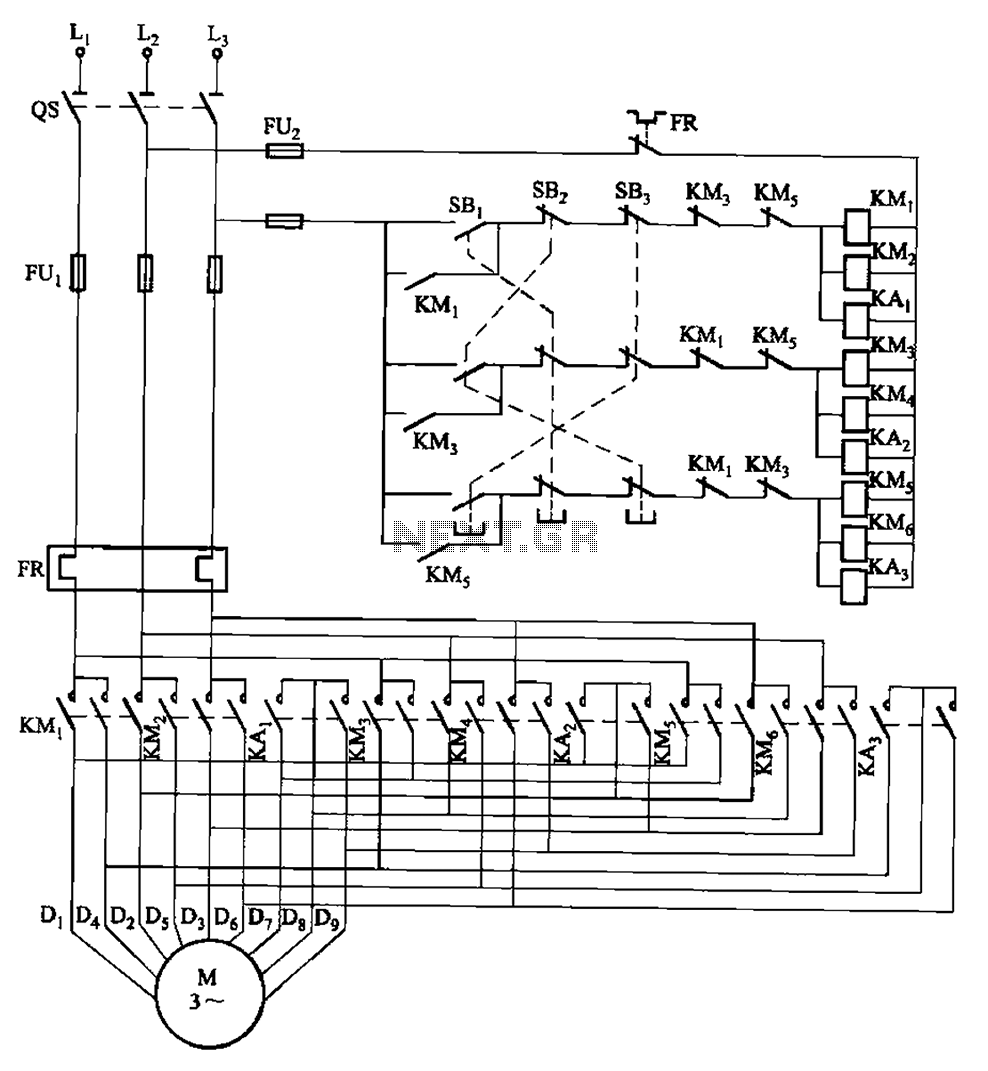
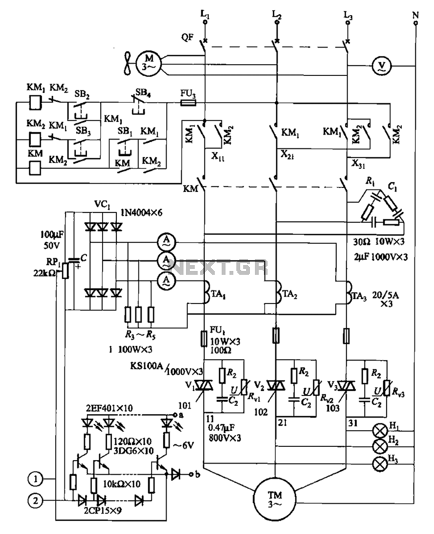
The circuit depicted in Figure 3-115 utilizes contactors and double buttons, allowing for speed conversion without the need to press the stop button. The buttons SBi, SBz, and SB3 correspond to high, medium, and low-speed operation, respectively. This circuit design...
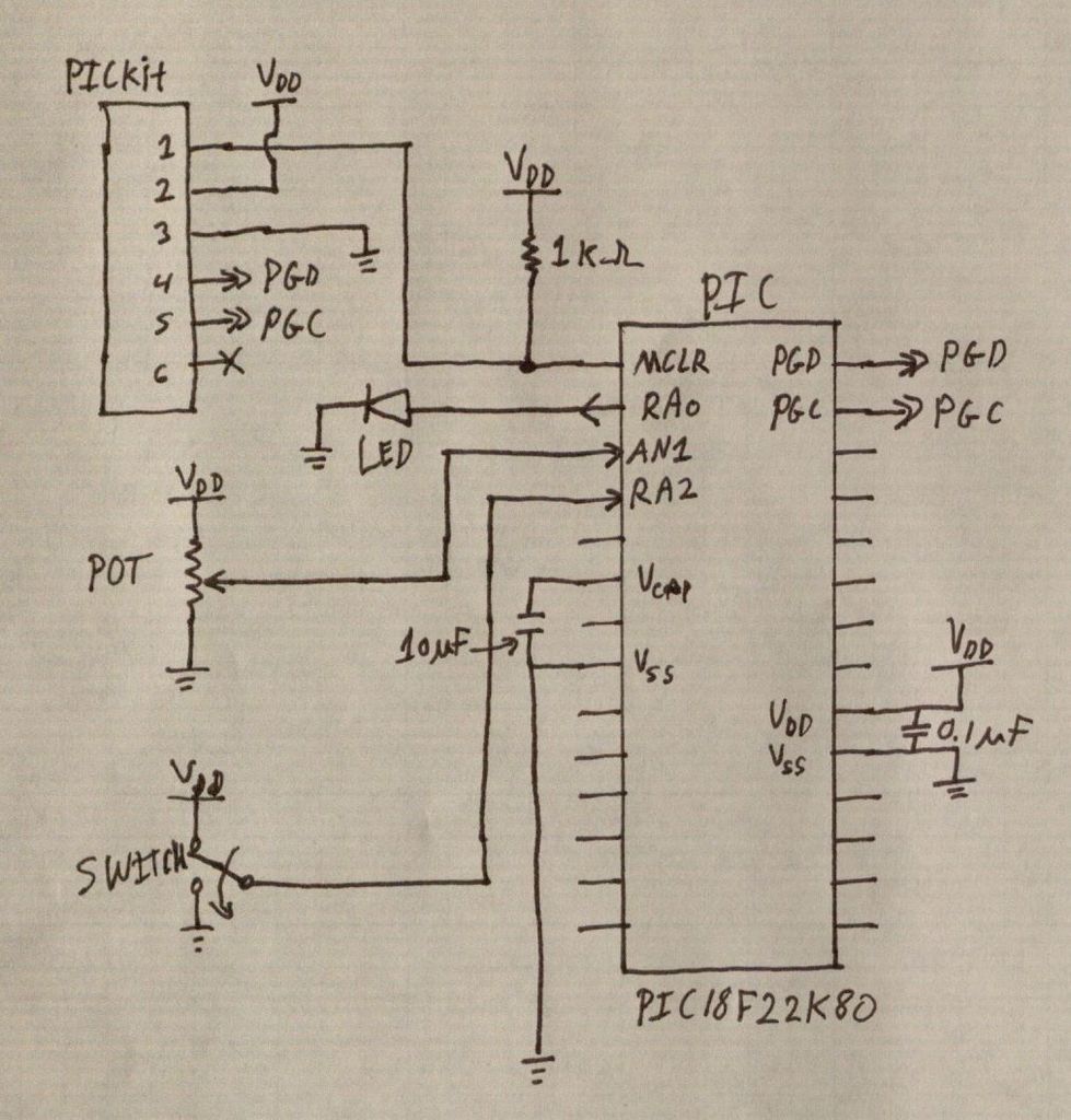
PIC microcontrollers are a highly useful and versatile component for various electronic projects. They are affordable and readily available. PIC microcontrollers are embedded systems that serve as the central control unit in a wide range of electronic applications. Their architecture...
The ULN2003 features high voltage, high current Darlington arrays, each consisting of seven open collector Darlington pairs with common emitters. The ULN2003 is a versatile integrated circuit designed for driving high-current loads such as relays, motors, and lamps. It...