These motors consist of two coils and are operated by altering the direction of current flow through the coils in a specific sequence. They feature only four wires and cannot be directly connected to this kit. Refer to Kit 1406 for a Bipolar Stepper Driver Kit. Unipolar motors, on the other hand, have two center-tapped coils that are utilized as four coils. These motors can have five, six, or eight wires. Five-wire motors have the two center-taps internally connected and brought out as one wire. Six-wire motors have each center-tap brought out separately, requiring external commoning of the two center-taps. Eight-wire motors have both ends of each coil brought out, with the four center-taps joined externally to form one wire. In all instances, the center-tap(s) are connected to a positive motor power supply. Unipolar motors can also be configured as bipolar motors by omitting the positive wires. A stepper motor operates without brushes or contacts, functioning essentially as a synchronous motor with an electronically switched magnetic field to rotate the armature magnet. For detailed explanations about stepper motors, online resources are available, including a prominent reference titled "Jones on Stepper Motors." The circuit design in this kit has been utilized in various forms for many years, with the latest publication appearing in Silicon Chip, 5/2002. This controller operates in both free-standing and PC-controlled modes. In free-standing mode, an internal square-wave oscillator, based on IC2:B of the 4093, generates timing pulses for the OSC output. The frequency of these pulses, and consequently the stepper motor's speed, is adjustable via a 100K trimpot (VR1). A series 1K resistor limits the maximum frequency, which can be modified as needed. These pulses are input to the STEP terminal, buffered and inverted by IC2:D to prevent false triggering. Similarly, IC2:C buffers and inverts the DIRection input. A single-pole double-throw (SPDT) switch connects the input to +5VDC or ground, controlling the rotation direction. IC3:C and D (4030 or 4070 exclusive OR gates) invert the outputs from the Q and /Q outputs of flip-flops IC4:A and IC4:B. The incoming step pulses clock the flip-flops, toggling the Q and /Q outputs, which sequentially turn the MOSFETs on and off. The IRFZ44 MOSFETs possess a low on-resistance and can handle up to 6A each without requiring a heatsink. The power supply for the stepper motor connects to the V+ and GND terminals as illustrated. A separate power supply, KITV, is used for the 78L05 voltage regulator to power the ICs, with 9V to 12V DC being adequate. R2/C2 form a low-pass filter to mitigate fast-rise switching transients from the motor. Some literature suggests using a 4070 instead of a 4030; however, testing with the 4030 has not indicated any issues. Feedback regarding this discrepancy is welcomed. In computer-controlled mode, connect to the three pads with pins DIR, STEP, and GND, and set the SPDT switch to EXTernal. In this mode, the direction SPDT has no effect. Eight-wire motors bring out both ends of each coil, with the four center-taps joined externally to form one wire, and the center-tap(s) connected to a positive motor power supply. A driver circuit is required to energize the rotor, which applies voltage to any of the four stator coils. This driver can be constructed using an integrated circuit like the ULN2003, four Darlington transistors, or four power transistors such as the 2N3055. After further testing, modifications to the values of the trimpot and R1 have been made from those indicated on the PCB overlay. It is advised to install the resistors and four links first, utilizing the cutoff lengths from the resistors for the links.These have two coils and are controlled by changing the direction of the current flow through the coils in the proper sequence. These motors have only four wires and cannot be connected to this kit. See our Kit 1406 for a Bipolar Stepper driver Kit. 2. Unipolar motors. These have two center-tapped coils which are treated as four coils. These motors can have five, six or eight wires. Five-wire motors have the two center-taps commoned internally and brought out as one wire (Fig 1). Six-wire motors bring out each center-tap separately. The two center-taps need to be commoned externally (Fig 2). Eight-wire motors bring out both ends of each coil. The four center-taps are joined externally to form one wire. In each case the center-tap(s) are connected to a positive motor power supply. Unipolar motors may be connect as bipolar ones by not using the +` wires. A stepper motor has no brushes or contacts. It is basically a synchronous motor with the magnetic field electronically switched to rotate the armature magnet around. The Internet is where to get all the explanation about steppers. Just google stepper motor` and you will find tens of sites. In particular, look for Jones on Stepper motors` (it comes up top of the list when I did it just now) and read it.
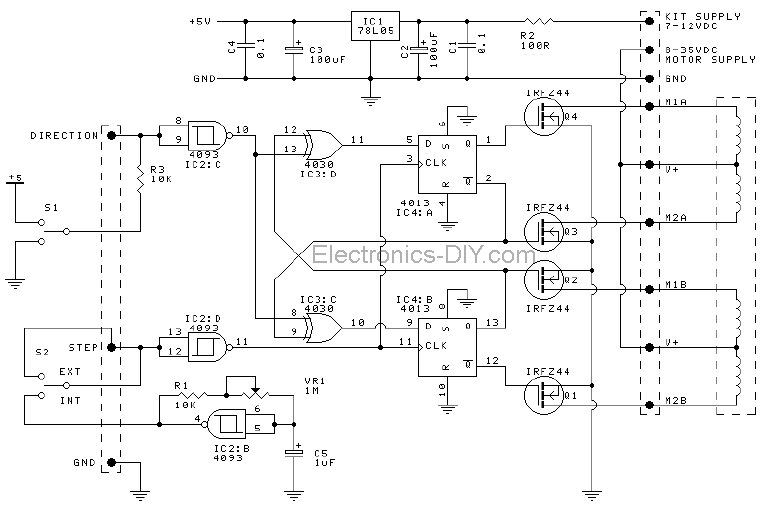
If you look at the other references you will find that the circuit in this kit has been around for many years in various forms. The latest publication was in Silicon Chip, 5/2002, and I have based this circuit on it. This controller works in either free-standing or PC controlled mode. In free-standing mode an internal square-wave oscillator based on IC2:B of the 4093 supplies timing pulses to the OSC output.
The frequency of these pulses and thus the speed of the stepper motor is controlled by the trimpot VR1 (100K. ) A series 1K resistor controls the maximum frequency. You may increase the value of this resistor for your own needs. These pulses are fed into the STEP input which is buffered and inverted by IC2:D. This helps prevent false triggering. Similarly, IC2:C buffers and inverts the DIRection input. A SPDT taking the input to +5VDC or ground controls the direction of rotation. IC3:C and D (4030 or 4070 exclusive OR gates) invert the outputs available at Q and /Q outputs of each of the flip-flops (FF) IC4:A and IC4:B.
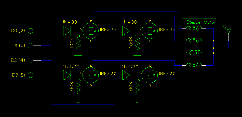
The incoming step-pulses clock the FF, thus toggling the Q & /Q outputs and this turns the MOSFET`s on and off in sequence. The IRFZ44`s have a low on-resistance and can deliver up to 6A each without needing a heatsink. Power to the stepper motor is connected to V+ and GND terminals as shown on the overlay. There is a separate power supply, KITV, to the 78L05 to power the IC`s. 9V 12VDC will be sufficient. R2/C2 form a low-pass filter to filter fast-rise switching transients from the motor. Note that some stepper motor texts say to use a 4070 instead of a 4030. We have not worked out why this is. Certainly our testing with the 4030`s showed no problems. I would like to hear from anyone who knows why this advice is sometime given. In computer-controlled mode use the three pads with pins DIR, STEP and GND. Switch the SPDT switch to EXTernal. The direction SPDT has no effect in external mode. (Fig 2). Eight-wire motors bring out both ends of each coil. The four center-taps are joined externally to form one wire. In each case the center-tap(s) are connected to a positive motor power supply. In able to move the rotor you will need a driver. Driver is a circuit that applies a voltage to any of the four stator coils. Driver can be built with IC such as ULN2003 (pictured on the circuit diagram), four darlington transistors or four power transistors such as 2N3055.
Note that after further testing we have changed the values of the trimpot and R1 from that shown on the PCB overlay. Put the resistors and 4 links in first. Use the cutoff lengths from the resistors for the links. Add the o 🔗 External reference
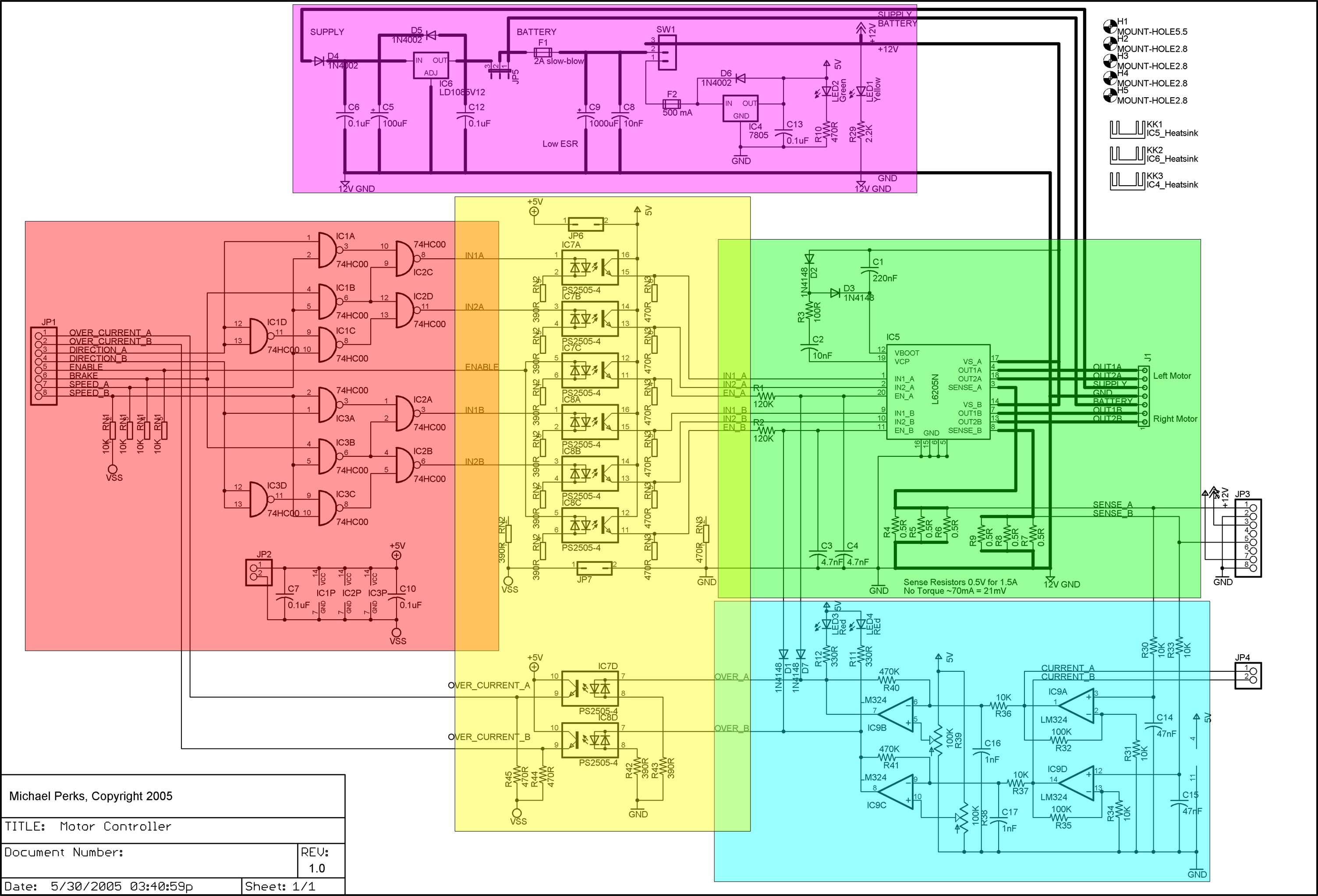
A dual DC motor controller employs an H-bridge controller chip. In addition to the standard features of the H-bridge driver chip, such as thermal and over-current protection, the circuit supports dual 12V/5V regulated power supplies, sign/magnitude and brake driver...
This design is based on one published by Milan Lulic in the German magazine elektroModell. Mr. Lulic's design is for surface mount technology (SMT) construction, whereas mine uses standard off-the-shelf components, and is therefore better suited to construction by...
Several individuals have encountered difficulties in locating the transformer required for the Black Light project. Consequently, a search was conducted to identify a fluorescent lamp driver that operates without the necessity for specialized components. A suitable option was discovered...
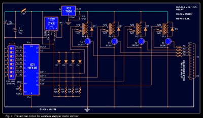
Stepper motors are widely used in applications such as process control, machine tools, and robotics. In particular, remote control of stepper motors is essential in robotics and process control. This document provides the circuit diagrams for both the transmitter...
The use of a PC's parallel port provides a convenient method for controlling a stepper motor. For unipolar stepper motors, it is possible to control up to two motors using the 8-bit data line. Typically, a Darlington driver, such...
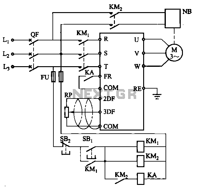
Electromagnetic brake motors consist of a motor and an electromagnetic brake, forming a standard assembly. The circuit diagram is provided. In this configuration, FR represents the forward run and stop command terminal, while the intermediate relay KA is employed...
Warning: include(partials/cookie-banner.php): Failed to open stream: Permission denied in /var/www/html/nextgr/view-circuit.php on line 713
Warning: include(): Failed opening 'partials/cookie-banner.php' for inclusion (include_path='.:/usr/share/php') in /var/www/html/nextgr/view-circuit.php on line 713