
stepper motor tester
The stepper motor tester circuit is designed to effectively evaluate both unipolar and bipolar stepper motors. The separation of the control and driver circuits allows for versatility in power supply selection, accommodating motors with voltages ranging from 5V to 24V. The inclusion of a clock generator, phase sequence logic, and power transistor drivers ensures precise control over the motor's operation. The use of a 74LS193 binary counter enables the generation of pulse sequences that dictate the direction of motor rotation, while the 74LS139 decoder facilitates the generation of the necessary four-phase signals for stepper motor operation.
The circuit's design prioritizes ease of use, featuring three switches that allow the operator to easily select the desired mode of operation, whether it be forward or backward movement or switching between wave and full-step drive modes. The wave drive method simplifies the control process by activating one coil terminal at a time, while the full-step drive method engages two transistors simultaneously, optimizing torque and performance.
The inclusion of Darlington NPN transistors enhances the driving capability of the circuit, allowing for efficient current handling and improved performance when driving the stepper motors. The H-bridge configuration utilized for bipolar motors is particularly noteworthy, as it enables bidirectional control of the motor, expanding the tester's functionality.
Attention to detail in wiring and polarity is critical to ensure proper motor operation and to avoid issues such as missed steps and vibrations. The tester's design accommodates various motor types and configurations, making it a valuable tool for testing and evaluating stepper motors in different applications. Overall, the stepper motor tester circuit stands as a robust solution for assessing the performance of both unipolar and bipolar stepper motors in a variety of settings.To build astepper motor tester, the circuit contains two sets of drivers that can support both unipolar and bipolar stepper motors. The control circuit and driver circuit are in separate power supplies that can work on a wider rangeof different power suppliesof motors.
Themotor driver can support motors with power supplies from 5V-24V. The stepper tester contains three major sections: the clock generator, phase sequence of waveform logic, and power transistor drivers. The 3 switches are used in the circuit for theselection offorwards / backwards movement, motor start-and-stop control, and a wave / full step drives.
The tester does not provide a half-step drive. In the circuit diagram, the clock signal from the oscillator connects to the 74LS193, an up/down binary counter. When theclock signal connectsto the count-up input, itwill generate the pulse sequence to the stepper motor in a clockwise direction.
It will turn counter-clockwise if the count-down input is used. The 74LS139 decodes the two-bit counter output and generate the 4-phase pulses to drive the stepper motors in the 4-phase terminals respectively. Driving the unipolar and bipolarstepper motors are the same, but each phase will pulse alternatively.
There are three methods used to drive, but the wave drive is the simplest way: a pulse is applied to each of the coil terminal at a time. The half-step applies pulses to one or two coils alternatively. This will create finer movements. The half-step drive will have double the amount of steps / revolution. As the torque is unequal in each step, it will cause more vibration. In the diagram, four Darlington NPN transistors are used to drive each coil terminal. Only 1 transistor is turned on at a time in a wave drive. In a full-step drive, it will always have 2 transistors turned on. In the bipolardriver diagram, four Darlington NPN power transistors form an H-bridge circuit to drive each coil in the bipolar stepper motor.
Two H-bridge drivers are needed for the four-wired bipolar stepper motor. Because the control circuit uses 5V (VCC) and the motor driver power supply is separated (V+ from 5V-24V), 2 additional transistors (Q13 & Q14, Q15 & Q16) are required for each H-bridge driver when the V+ voltage supply is more than 5V to drive the higher voltages stepper motors. Below are three basic wirings of typical stepper motors. The polarity of the phase terminals are very important. It can affect the direction of the rotation, which will lose steps andexcess vibration if wired incorrectly.
When the 6-wired stepper motor is driven by the bipolar drivers in 4-wired configuration, the power supply needs to be higher than the rated unipolar voltage because it operates in a full coil. Also voltage does not always have to be doubled, it depends on the power rating specifications from the motor.
One of the simplest ways is to find the stepper motors wiring, click here. The pictureshows a testing for the 6-wired stepper motor, which was removed from a HP LaserJet III printer. This steppermotor is made by Japan Servo Co. Ltd. , part number RH7-1048. It is marked with5. 2V at 1. 4A per phase in a rated unipolar drive. The resistance is measured at about 3. 5 ohms to the center tap. The tester is driving the motor at a 5V power supply in a unipolar driver. If the motor is using bipolar drivers, first, calculate the power rating of the coil. The voltage supply should be about 7V at 1A per phase. The picture shows a testing for an ink jet printermotor that is a 4-wired bipolar stepper motor. The motor has no information is povided, but traces of the printer circuit estimates the motor to be about 12V.
The coil`s resistance is about 4. 5 ohms as it is being tested in 12V power supply in bipolar drivers. Many of the stepper motors used in printers are in 24V supply and a 7. 5 degree/step. 🔗 External reference
Related Circuits

This is a simple hobby circuit for a remote-controlled toy car. The primary component utilized is the IR sensor circuit, which includes a TSOP IR receiver. This receiver allows the user to start and stop the DC motor of...
A designer often needs to know the internal resistance value of a battery. Many testers provide a relative indication of this value, but it is seldom expressed in ohms. The current tester can, in principle, provide this information. The...

The servo motor is a type of traditional motor that serves as the execution component in automated devices. Its most significant characteristic is its controllability; when a control signal is applied, the servo motor rotates, with its speed being...
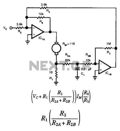
This circuit provides bidirectional speed regulation for small motors and does not require a tachometer. The voltage applied to the motor's windings, which is determined by summing amplifier IC1A, is expressed as a function of the command voltage (Vc)...
The circuit is illustrated in Figures 16-95 to 16-97. The electrode automatic adjuster demonstrates enhanced performance, featuring a high-accuracy, well-linear current output type bridge. Additionally, it incorporates a differential arc current negative feedback circuit (advanced) that allows for preemptive...
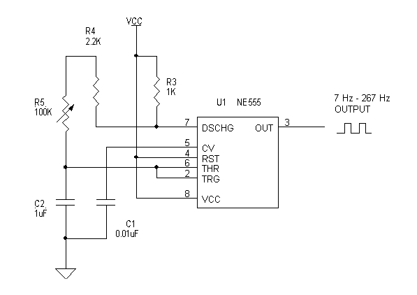
Individuals who frequently work with servos are likely familiar with situations where a servo tester is beneficial. The primary function of a servo tester is to produce a pulsing signal with a variable positive pulse width ranging from 1...