Stepping-motor-drive

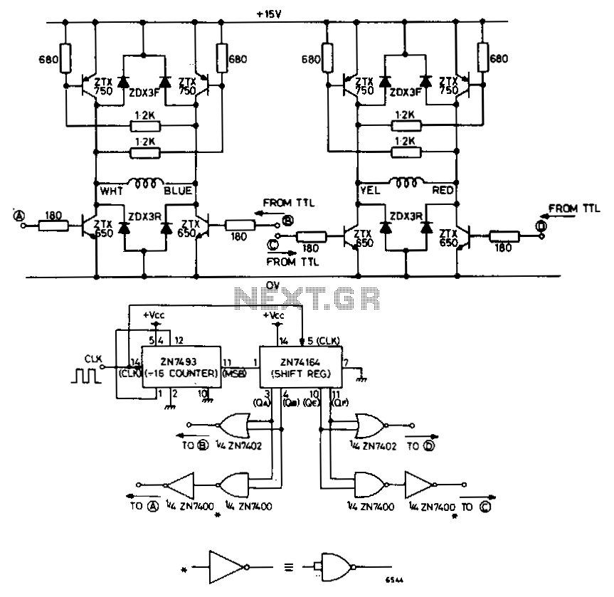
The circuit depicted in Fig. 62-15A is intended to drive a 15-V, two-phase, bipolar stepping motor, delivering a bidirectional single-level voltage across each winding with currents reaching up to 9.6 A. It comprises two identical transistor bridge stages that utilize complementary npn and pnp transistors. The conduction sequence of the transistors is dictated by external control logic, allowing the circuit to interface directly with standard TTL. A suitable control logic system is presented in the accompanying diagram.
The circuit functions by utilizing a dual H-bridge configuration, where each bridge controls one phase of the stepping motor. The complementary nature of the transistors allows for efficient switching and control of the motor phases. When a high signal is applied to the control logic inputs, the respective npn and pnp transistors are activated, allowing current to flow through the motor windings in the desired direction. This bidirectional control is essential for the operation of stepping motors, which require precise control over the direction of rotation.
The design ensures that each transistor can handle the maximum current of 9.6 A, providing sufficient power for the motor's operation. The use of standard TTL logic for control simplifies integration with other digital systems, allowing for easy interfacing with microcontrollers or other digital signal sources. The control logic diagram likely outlines the necessary connections and logic levels required to achieve the desired stepping sequence, enabling smooth and accurate motor movement.
In summary, this circuit is a robust solution for driving bipolar stepping motors, leveraging a well-designed transistor bridge configuration and compatible control logic to achieve high-performance operation in various applications.The circuit shown in Fig. 62-15A is designed to drive a 15-V, two-phase, bipolar stepping motor, providing a bidirectional single level voltage across each winding at currents of up to 9.6 A. The circuit consists of two identical transistor bridge stages employing complementary npn and pnp devices.
The transistor conduction sequence is determined by external control logic, and the circuit will interface directly with standard TTL. A suitable control logic system is illustrated in diagram.