
Stereo decoder circuit using MC1310P
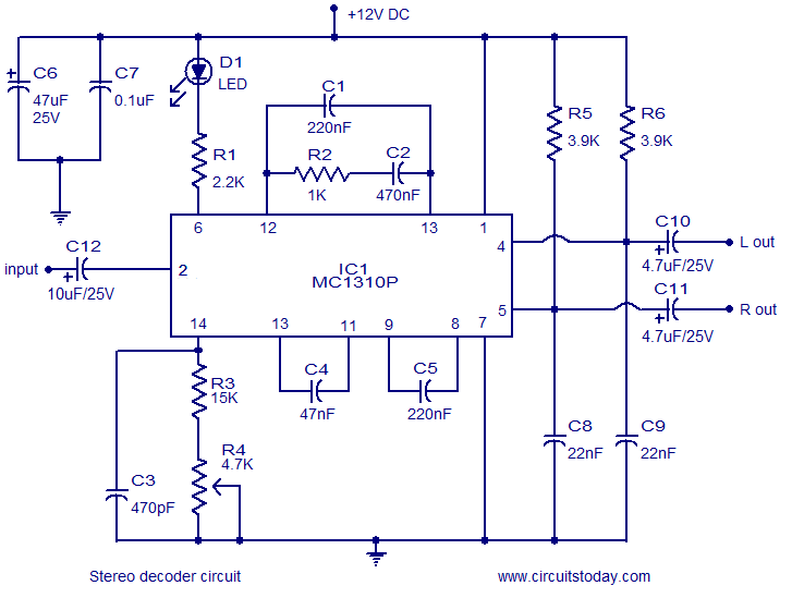
The FM stereo decoder circuit based on the MC1310P IC is designed to demodulate FM stereo signals efficiently while ensuring high fidelity audio output. The MC1310P is a versatile and widely used IC that integrates various functions necessary for stereo FM demodulation, including the processing of multiplexed audio signals.
The circuit typically operates with a power supply of 12V, which is standard for many consumer electronics, ensuring compatibility with a wide range of FM receiver applications. The 40dB channel separation is a critical specification, as it indicates the ability of the circuit to distinguish between the left and right audio channels. This separation is essential for delivering a clear and immersive stereo sound experience.
In the implementation of this circuit, the MC1310P requires external components such as resistors, capacitors, and inductors to form the necessary filters and to set the appropriate operating parameters. The input stage usually involves an RF front-end that captures the FM signal from an antenna, which is then fed into the MC1310P for demodulation.
Output from the MC1310P can be directly connected to audio amplifiers or further processing stages, depending on the design requirements. The circuit's architecture allows for adjustments in gain and filtering to optimize audio quality and performance, making it adaptable for various applications in stereo FM receivers.
Overall, this simple FM stereo decoder circuit is an effective solution for converting FM signals into high-quality stereo audio, suitable for both hobbyist projects and commercial audio applications.Simple FM stereo decoder circuit using MC1310P IC. 12V operation, 40dB channel seperation. Suitable for stereo FM receivers.. 🔗 External reference
Related Circuits
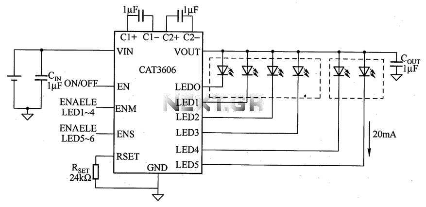
CAT3606 is a high-efficiency white LED driver. This adjustable charge pump is suitable for general-purpose, large-panel, flicker-free white LED backlighting and dual-display systems. The CAT3606 inductor boost circuit can replace conventional high-brightness backlighting requirements, thereby simplifying system design. It...
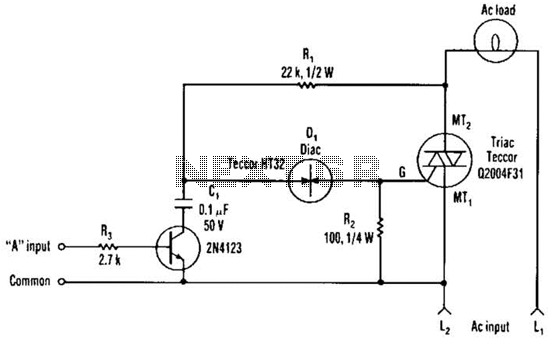
The single transistor connected between the capacitor and the common side of the AC line allows a logic-level signal to control this TRIAC power circuit. Resistor R2 prevents false triggering of the TRIAC by the trickle current through the...
This radio receiver can operate with any of the following transistors: ZN414, MK484, or TA7642. The radio receiver circuit is designed to utilize a variety of transistors, specifically the ZN414, MK484, and TA7642, which are commonly used in low-power AM...
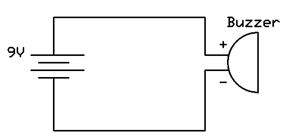
This project involves connecting the positive terminal of the battery to the positive lead of the buzzer and the negative terminal of the battery to the negative lead of the buzzer. Typically, the positive lead of the buzzer is...
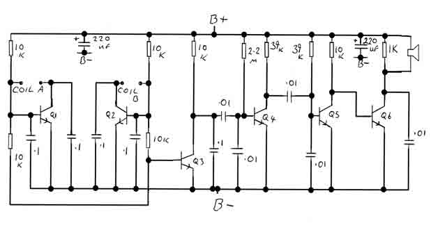
By adjusting the oscillators so their frequencies are very nearly the same, the difference between them is made audible as a beat note. This beat note changes slightly when the search loop is moved over or near to a...
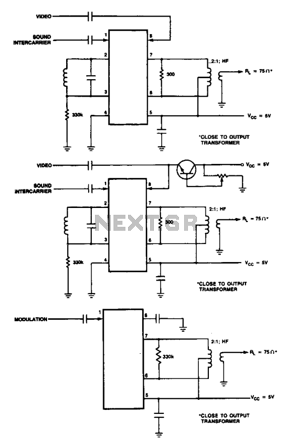
These are modulator circuits designed for the modulation of video signals on a VHF/UHF carrier. The circuits require a 5 V power supply and a few external components for negative modulation mode. For positive modulation, an external clamp circuit...
Warning: include(partials/cookie-banner.php): Failed to open stream: Permission denied in /var/www/html/nextgr/view-circuit.php on line 713
Warning: include(): Failed opening 'partials/cookie-banner.php' for inclusion (include_path='.:/usr/share/php') in /var/www/html/nextgr/view-circuit.php on line 713