
Stereo Electret Mic Preamplifier
The stereo electret microphone preamplifier circuit employs the LM358 operational amplifier, which is configured to amplify the low-level audio signals from an electret microphone. The use of solid or film capacitors helps to ensure low noise and high-frequency performance, while metal film resistors contribute to improved accuracy and stability of the gain. The circuit typically incorporates a gain-setting resistor (R5) that can be adjusted between 100K and 1M to accommodate different microphone sensitivities.
The additional component, the LM4809, serves as a stereo headphone amplifier, which is particularly useful in applications requiring audio amplification for headphones. This integrated circuit is designed to drive headphones directly, providing a clean audio output with minimal distortion. Its ability to deliver 105mW per channel makes it suitable for a variety of audio applications, ensuring compatibility with both low-impedance and high-impedance headphones.
The 2N3904 transistor preamplifier circuit is another valuable addition, as it provides a simple solution for boosting weak audio signals. This circuit can be easily integrated into RF transmitter designs, enhancing sensitivity to sound and allowing for effective audio transmission over radio frequencies.
Dynamic microphones, known for their durability and versatility, are well-suited for this type of application. Their robust construction allows them to handle high sound pressure levels, making them ideal for live sound reinforcement and studio recording.
The three-stage FM transmitter circuit, designed for a 9V power supply, exemplifies a compact and efficient method for wireless audio transmission. The use of BC547 transistors in the initial stages ensures reliable amplification of the audio signal before it is transmitted via the RF output stage. The design considerations for this transmitter include antenna matching and power supply stability to maximize transmission range and quality.
Finally, the tube microphone preamplifier circuit utilizing the 12AX7 tube offers a high-fidelity audio solution for those with advanced construction skills. This circuit is characterized by its warm sound quality and is often favored in professional audio applications. The specific voltage ratings for capacitors and the tolerance for resistors are critical for ensuring the circuit operates reliably within its intended parameters.This a simple stereo electret microphone pre amplifier circuit. For maximum performance, use solid capacitors or film capacitors and metal film resistors. Here the simple audio mic pre amplifier circuit based on single IC LM358. The circuit is very simple, inexpensive and easy to built. Component Parts List: R1, R3, R4 = 10K R2 = 1K R5 = 100K-1M Potensiometer C1 = 0. 1uF C2 = 4. 7uF/16V IC1 = LM358 dual op-amp single supply Mic = Electret Microphone. This is the stereo headphone amplifier circuit diagram, built based LM4809. This circuit can be used for stereo headphone amplifier circuit for home audio system, microphone preamplifier, personal computers and PDA headphone amplifier and more. The LM4809 is known as a stereo audio power amplifier capable of delivering 105mW per channel of continuous average power.
This is a simple audio Pre-Amplifier with single transistor 2N3904. This easy circuit provides good gain to weak audio signals such as electret microphone. Use it in front of an RF oscillator to make an RF transmitter that`s very sensitive to sound. This circuit should be perfect for dynamic microphone. Dynamic microphones are versatile and ideal for general-purpose use. They use a simple design with few moving parts. They are relatively sturdy and resilient to rough handling. They are also better suited to handling high volume levels, such as from certain musical instruments or amplifiers. They have. This circuit is a powerful three stage, 9V FM transmitter (Tx) with a range of up to 1 kilometer in the open.
It uses an RF transistor in its output stage and two BC547`s for the first two stages. Distance of trans-mission is critically dependent on the operating Conditions (in a building or out on. The following diagram is the circuit diagram of tube mic pre amplifier 12AX7. This circuit is little hard to built. You must have an intermediate or advanced skills to build this circuit. All capacitors with value of 33uF are 16V, while the all others are 50V unless marked otherwise. Resistors marked with "#" are 1%. 🔗 External reference
Related Circuits
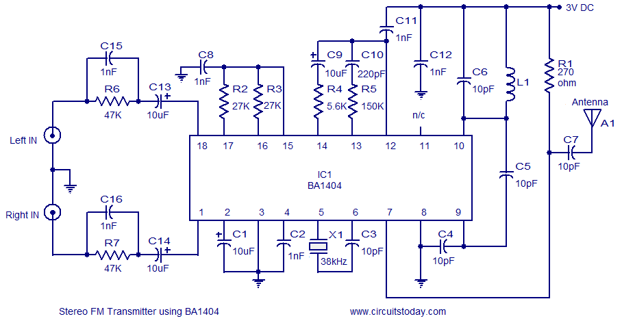
A high-quality stereo FM transmitter circuit is presented. This circuit utilizes the BA1404 integrated circuit from ROHM Semiconductors. The BA1404 is a monolithic FM stereo modulator that incorporates a stereo modulator, FM modulator, and RF amplifier circuitry. The FM...
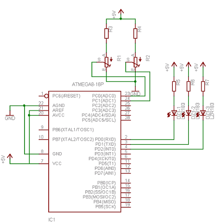
Neural networks are a broad topic. This example demonstrates how to create a basic neural sensor that takes resistive readings from multiple sensors, multiplies them by a weight factor, and then sums the results. The results are compared to...
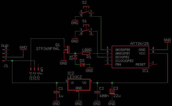
This document serves as a continuation of the previous work on PWM controllers utilizing 555 timers. The new design incorporates microcontrollers and MOSFETs in place of the 555 integrated circuits and transistors. Two versions have been developed: one equipped...
Diode D1 and resistor R1 provide VDD isolation during the programming of 24-pin devices. The jumper J3 must be shorted for 24-pin device programming and left open for 28-pin device programming. The following EEPROMs are pin-compatible with their EPROM...
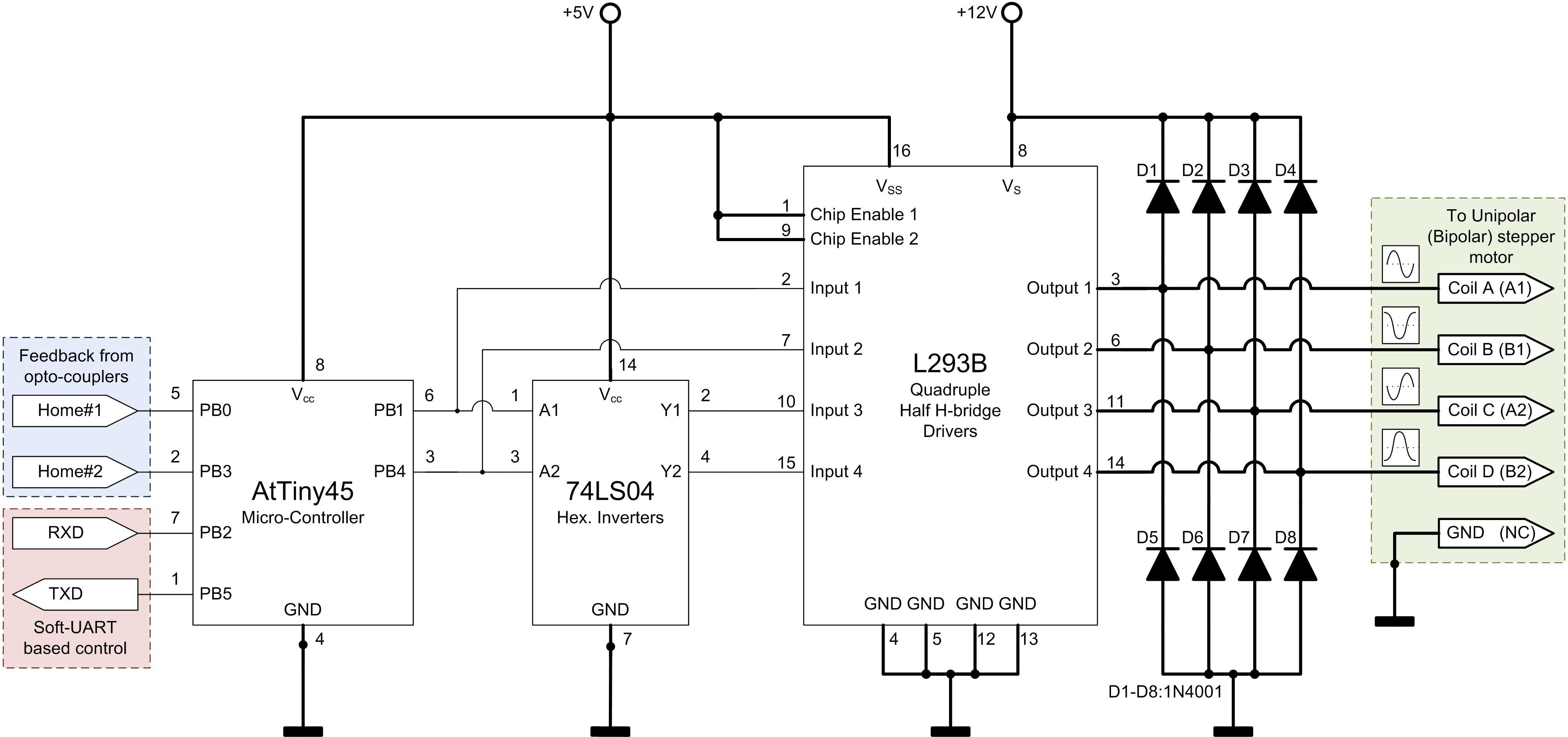
In a traditional microstepping motor controller, multiple parallel outputs from a microcontroller are utilized, which are then converted to analog signals using a Digital-to-Analog Converter (DAC) and sent through a power amplifier to drive the motor coils. This method...
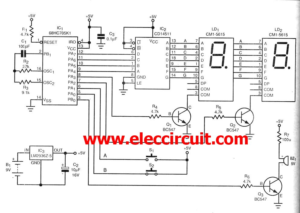
The microcontroller IC is a device that resembles a typical integrated circuit. However, it contains a miniature computer within its architecture. This device can serve as a replacement for transistors. Microcontroller integrated circuits (ICs) are compact, multifunctional devices that integrate...