
Stereo Encoder Circuit
The stereo encoder circuit utilizes the MMC4066E, which is a quad bilateral switch, to manage the audio signals effectively. This IC is responsible for switching the audio channels, allowing for the separation of left and right audio signals, essential for stereo sound. The MMC4047, on the other hand, functions as a timing and frequency generation IC, which can facilitate the modulation of the audio signals for encoding purposes.
The BC547B transistor serves as a buffer or amplifier in the circuit, ensuring that the output signals maintain their integrity and strength when transmitted to the subsequent stages or to the output device. The configuration of these components allows for a compact and efficient stereo encoding solution suitable for various audio applications.
In a typical setup, the audio inputs are fed into the MMC4066E, where they are processed and switched according to the control signals provided by the MMC4047. The output from the MMC4066E is then amplified by the BC547B, ensuring that the final stereo output is clear and powerful enough for driving speakers or other audio devices. Proper power supply decoupling and grounding techniques should be employed to minimize noise and ensure stable operation of the circuit.This simple stereo encoder circuit schematic is build with 2 IC MMC4066E and MMC4047 and one transistor BC547B. On IC1 2 and 3 pins is the audio output whi.. 🔗 External reference
Related Circuits
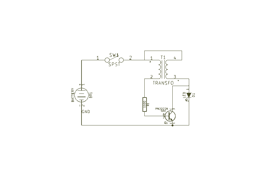
Easy Joule Thief Soldering Kit from MakersBox on Tindie The Easy Joule Thief Soldering Kit is designed for educational purposes, allowing users to learn about basic electronics through hands-on experience. This kit includes all necessary components to assemble a Joule...
This characterization circuit, along with a PC and specific software, accurately measures the complete discharge cycle of a rechargeable AA cell. The capacity and output resistance of the cell can be easily determined from the resulting curve of these...

The simple 4-digit converter circuit has an output count of 1, designed for a frequency range from f-IMHz to 10.000 MHz. All diodes used in the circuit are IN4146 "POLYSTYRENE" NPO. The circuit utilizes the LF398 at the input...
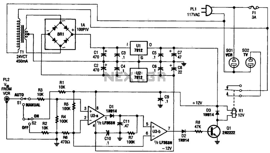
This circuit detects the video signal from the VCR. When the VCR is powered on, the video signal is amplified by U3A to drive Q1, which activates K1. This setup eliminates the need to manually turn on and off...
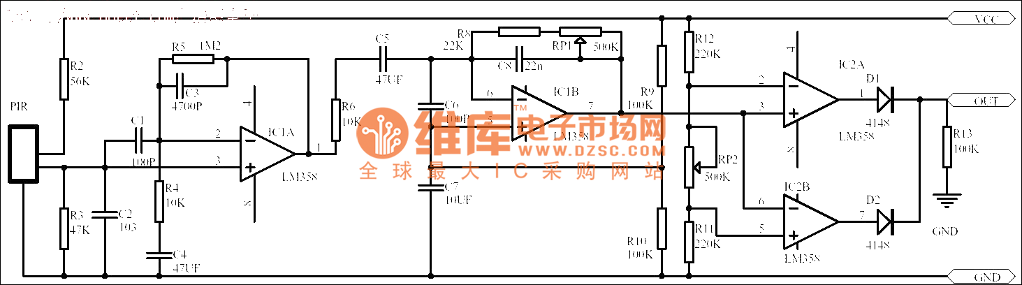
Passive human body infrared sensor circuits are generally similar in design, although some may have fewer stages. The circuit illustrated is sourced from the NICERA manufacturer and is considered a classic example. The front-end stage consists of a low-frequency...
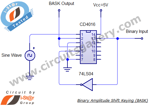
Binary Amplitude Shift Keying (BASK), also known as On-Off Keying (OOK), is a digital modulation technique where the amplitude of the carrier signal is altered according to binary data. This modulation scheme is utilized for transmitting digital information over...