
Stereo-indicator
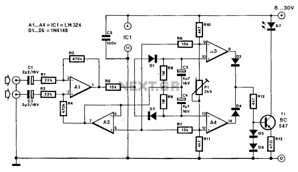
On most FM tuners, the stereo indicator activates upon detection of the 19-kHz pilot tone. However, this does not guarantee that the program is actually stereophonic, as the pilot tone is frequently transmitted alongside mono programs. A similar scenario occurs in stereo amplifiers, where the stereo LED is merely controlled by the mono/stereo switch. The LED-based stereo indicator described here illuminates only when a genuine stereo signal is input. More specifically, differential amplifier A1 amplifies the difference between the left (L) and right (R) input signals. When these signals are equal, the output of A1 remains at the same potential as the output of A2, which creates a virtual ground rail at half the supply voltage. When A1 detects a disparity between the L and R input signals, it generates a positive or negative voltage relative to the virtual ground rail, thereby charging capacitor C3 through diode D1 or capacitor C4 through diode D2. Comparator A3/A4 activates the LED driver via the OR circuit formed by diodes D3 and D4. The input signal level must not fall below 100 mV to account for the voltage drop across diodes D1 or D2. The sensitivity of the stereo indicator can be adjusted using potentiometer P1.
The circuit described serves as a reliable stereo indicator for audio systems, ensuring that the user is informed only when an authentic stereo signal is present. The differential amplifier A1 plays a critical role in distinguishing between the left and right audio channels. By comparing these signals, A1 can determine whether they are equal or exhibit a difference. The concept of a virtual ground rail at half the supply voltage is essential for providing a stable reference point for the output of A1, facilitating accurate voltage comparisons.
When a difference is detected, A1 generates a corresponding voltage that either charges C3 or C4, depending on the polarity of the signal difference. Capacitors C3 and C4 act as storage elements that help to maintain the charge long enough for the LED indicator to respond appropriately. The diodes D1 and D2 ensure that the charging path is directed correctly, allowing only the intended capacitor to charge based on the output of A1.
The use of comparator A3/A4 is crucial for controlling the LED driver. This component processes the voltage signals from the capacitors and determines whether the LED should be activated. The OR circuit formed by diodes D3 and D4 allows for redundancy in the signal path, ensuring that the LED will illuminate if either capacitor indicates a sufficient voltage level.
Adjustable sensitivity via potentiometer P1 allows for fine-tuning of the stereo indicator's response, accommodating variations in input signal strength and ensuring optimal performance across different audio sources. The requirement for a minimum input signal level of 100 mV is an important design consideration, as it prevents false triggering of the LED due to noise or low-level signals. This feature enhances the reliability of the stereo indicator, providing users with a clear and accurate representation of the audio signal being processed.On most FM tuners, the stereo indicator lights upon detection of the 19-kHz pilot tone. However, this doesn"t mean that the program is actually stereophonic, since the pilot tone is often transmitted with mono programs also. A similar situation exists on stereo amplifiers, where the stereo LED is simply controlled from the mono/stereo switch.
The LED-based stereo indicator described here lights only when a true stereo signal is fed to the inputs. Differential amplifier Al raises the difference between the L and R input signals. When these are equal, the output of Al remains at the same potential as the output of A2, which forms a virtual ground rail at half the supply voltage. When Al detects a difference between the L and Rinput signals, it supplies a positive or negative voltage with respect to the virtual ground rail, and so causes C3 to be charged via Dl or C4 via D2.
Comparator A3/A4 switches on the LED driver via OR circuit D3/D4. The input signal level should not be less than 100 mV to compensate for the drop across Dl or D2. The sensitivity of the stereo indicator is adjustable with Pl. 🔗 External reference