
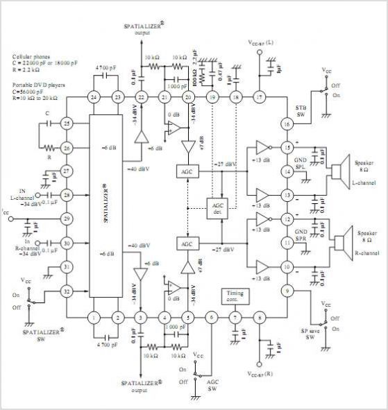
Stereo OTL Audio Amplifier
The Stereo OTL Audio Amplifier circuit utilizes integrated circuits to simplify the design and implementation process. The choice of ICs—LM379, LM377, and LM378—provides flexibility in terms of power output and supply voltage, allowing users to select the appropriate component based on their specific requirements.
The LM379, with a maximum supply voltage of 28V, offers the highest power output of 4W per channel, making it suitable for applications requiring robust sound amplification. The LM377, while limited to a maximum of 18V, still provides a respectable output of 2W per channel, ideal for smaller audio setups. The LM378, operating at a maximum of 24V, delivers 3W per channel, striking a balance between power and voltage supply.
In audio amplification systems, the role of the amplifier is crucial. It takes low-power audio signals, often originating from various audio sources, and boosts them to a level that can effectively drive loudspeakers. This process is essential in ensuring that sound reproduction is clear and powerful, enhancing the overall listening experience. The circuit design typically includes various stages, with the audio amplifier being the final stage, ensuring that the output is suitable for playback on loudspeakers.
The circuit can be further enhanced by integrating additional components such as capacitors for filtering and resistors for setting gain levels. Proper layout and grounding techniques are essential to minimize noise and interference, ensuring high-quality audio output. The simplicity of the design allows for easy troubleshooting and modifications, making it an excellent project for both beginners and experienced electronics enthusiasts.
For those interested in practical applications, the video tutorial on building a simple audio amplifier with the LM386 chip serves as a valuable resource, demonstrating the feasibility of constructing an effective audio amplification solution at a low cost. This project exemplifies the principles of audio amplification and provides insights into the design considerations necessary for achieving high-fidelity sound reproduction.The following diagram is the circuit of Stereo OTL Audio Amplifier. It based on IC circuit, so the circuit looks simple. You can use IC LM379, LM377, LM378 for this amplifier project. Refer to the table, maximum voltage supply for IC LM379 is 28V, it will will deliver 4W/channel. For LM377, maximum Vcc voltage is 18V single supply and delivers about 2W/channel. While for LM378, use maximum 24V regulated DC power supply and you will get 3W hifi audio power per channel. An audio amplifier is an electronic amplifier that amplifies low-power audio signals (signals composed primarily of frequencies between 20 - 20 000 Hz, the human range of hearing) to a level suitable for driving loudspeakers and is the final stage in a typical audio playback chain.
The preceding stages in such a chain are low power audio amplifiers which perform tasks like pre-amplification, equalization, tone control, mixing/effects, or audio sources like record players, CD players, and cassette players. Most audio amplifiers require these low-level inputs to adhere to line levels. While the input signal to an audio amplifier may measure only a few hundred microwatts, its output may be tens, hundreds, or thousands of watts.
More explanation about power audio amplifier can be found at wikipedia. org This is a video tutorial about how to a very simple audio amplifier based on the LM386 amplifier chip. It can be built for less than $20 (or might be less than $8 in some countries) and used to amplify any low level audio signal including a guitar, bass or mp3 player.
🔗 External reference
Related Circuits
The TDA7294 is a high-fidelity amplifier capable of delivering 100W RMS with a distortion level of 10%. When supplied with 30 volts, it can output 50 watts RMS with a distortion level of 1%. The frequency response ranges from...
The following circuit illustrates the IC BA1404 used in a stereo FM transmitter circuit diagram. Features include ease of construction, making it accessible for anyone to build. The BA1404 is a versatile integrated circuit designed specifically for FM transmission applications....
AN12979A is a stereo BTL amplifier that includes an AGC circuit to prevent clipping at the speaker output. This integrated circuit (IC) can perform mode changes via the I2C bus control system, allowing for functions such as toggling the...
Install the red LED at D2. Align the flat side of the LED with the PCB outline. Install a jumper wire at R4 and install a 220µF electrolytic capacitor at C8 with the negative side connected to ground. Connect...
Amplifying circuit diagram to enhance the output current and voltage. An amplifying circuit is designed to increase the amplitude of an input signal, resulting in a higher output current and voltage. This type of circuit is commonly utilized in various...
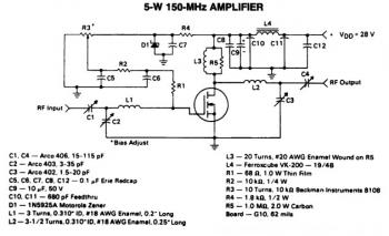
This is a 5W -150MHz RF amplifier circuit that utilizes the MRF123 TMOSFET. The MRF123 is a high-gain FET which may exhibit instability at both VHF and UHF frequencies; therefore, a 68 Ohm input loading resistor is employed to...
Warning: include(partials/cookie-banner.php): Failed to open stream: Permission denied in /var/www/html/nextgr/view-circuit.php on line 713
Warning: include(): Failed opening 'partials/cookie-banner.php' for inclusion (include_path='.:/usr/share/php') in /var/www/html/nextgr/view-circuit.php on line 713