
Stereo-power-meter
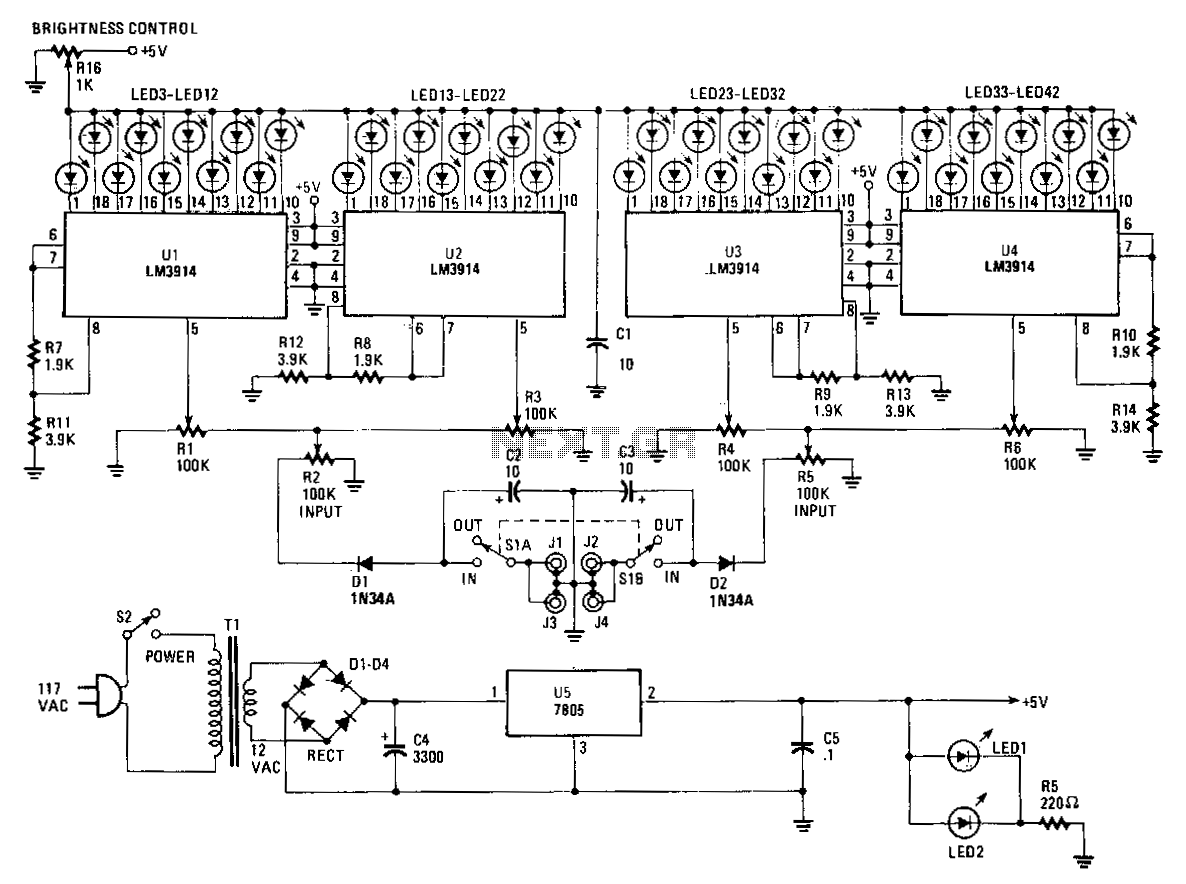
The Stereo Power Meter consists of two identical circuits and a power supply. Each circuit features two LM3914 display chips, which include 10 voltage comparators, a 10-step voltage divider, a reference voltage source, and a mode-select circuit that allows for the selection of a bar or dot display via a logic input at pin 9. The brightness of the LEDs is regulated by 1.9 kΩ resistors, while the reference voltage is controlled by 3.9 kΩ resistors. The 10-step voltage divider within the chips is connected between the reference voltage and ground. Each step of the voltage divider is separated by a 1 kΩ resistor, enabling each comparator to sense a voltage that is 10% greater than the previous comparator. The input signal is applied to pin 5, buffered through a resistor-diode network, and amplified before reaching each of the 10 comparators. Each LED is grounded through the comparators when the input signal voltage matches the reference voltage, leading to the illumination of one to ten LEDs as the signal voltage increases.
The Stereo Power Meter is designed to provide a visual representation of power levels in audio applications. The core of the device comprises two LM3914 display chips, which function as LED bar graph or dot matrix displays. Each chip operates independently, allowing for simultaneous monitoring of two channels. The LM3914 chips are equipped with ten voltage comparators that compare the input signal voltage against a reference voltage.
The voltage divider within the LM3914 chips is a critical component, consisting of ten 1 kΩ resistors configured in series. This arrangement generates ten distinct voltage levels, each spaced 10% apart from the reference voltage. The reference voltage is supplied by a dedicated source, adjustable through the 3.9 kΩ resistors, allowing for calibration of the meter to match the desired input range.
When an input signal is applied to pin 5 of each LM3914, it is buffered through a resistor-diode network to ensure that the signal is stable and free from noise. This buffered signal is then amplified, allowing it to effectively drive the voltage comparators. As the input signal rises and matches the reference voltage, the comparators activate the corresponding LEDs. The mode-select circuit enhances versatility by permitting the user to switch between bar and dot display modes, which can be useful depending on the application's requirements.
The brightness of the LEDs is controlled by the 1.9 kΩ resistors, which limit the current flowing through each LED. This feature not only extends the lifespan of the LEDs but also ensures consistent visibility across the display. The overall design of the Stereo Power Meter emphasizes precision and clarity, making it an essential tool for audio engineers and enthusiasts seeking accurate power level monitoring.The Stereo Power Meter is made up of two identical circuits and a power supply. Each circuit contains Jwo LM3914 display chips which contain 10 voltage comparators, a 10-step voltage divider, a referencevoltage source, and a mode-select circuit that selects a bar or dot display via a logic input at pin 9. The brightness of the LEDs is controlled by the 1900-!l resistors and the reference voltage is controlled by the 3900-!l resistors.
The 10-step voltage divider within the chips is connected between the reference voltage and ground. Since each step of the voltage divider is separated by a 1-K!l resistor, each comparator senses a voltage 1 O% greater than the preceding comparator.
The signal is applied to pin 5, which is buffered through a resistor-diode network and then amplified as it passes to each of the 10 comparators. Each LED is grounded through the comparators as the input signal voltage matches the reference voltage.
That results in one to 10 LEDs illuminating as the signal voltage increases. 🔗 External reference