
Stereo TV Decoder Circuit
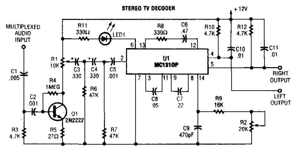
The MC1310P is a monolithic integrated circuit designed for stereo FM demodulation, specifically tailored for television applications. In this circuit, the MC1310P effectively demodulates the FM signal to retrieve the audio components. The audio amplifier, represented by transistor Q1, enhances the output audio signal, ensuring adequate volume levels for playback.
The circuit operates by utilizing a 31.5 kHz subcarrier frequency, which is critical for the demodulation process. This frequency is close to the standard FM multiplex frequency of 38 kHz, enabling the circuit to effectively process stereo audio signals. The pilot frequency of 15.734 kHz is also essential for stereo decoding, providing a reference tone that aids in distinguishing between left and right audio channels.
Despite its utility, the MC1310P has limitations, particularly in its inability to decode modern radio stereo signals due to differing frequency standards. The emergence of newer integrated circuits, such as the LM4500, offers enhanced performance and features that may be more suitable for contemporary applications. The LM4500 is designed to work with FM tuners and is available as a kit with a printed circuit board, facilitating easier implementation for hobbyists and engineers.
Overall, while the MC1310P remains a viable option for basic stereo TV decoding, advancements in technology have led to the development of superior alternatives that provide greater flexibility and improved audio quality in modern electronic designs.A simple stereo tv decoder circuit build with MC1310P. Transistor Q1 is an audio amplifier and U1 is used as a 31. 5KHz subcarrier which is similar to 38KHz FM MPX. Pilot frequency is 15. 734KHz. No, it cannot be used with the to decode the stereo signal. Radio stereo signal has a different frequency. The MC1310P is used in the SAE 3200 Stereo FM t uner. There are newer and better IC`s today. LM4500 Bob in the FM Tuner group makes a kit with PC board for this one. Ed 🔗 External reference
Related Circuits
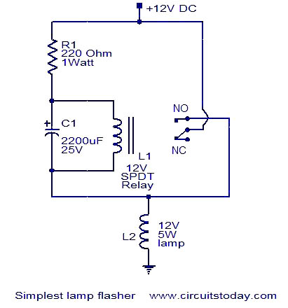
This is a simple lamp flasher circuit that utilizes only three components (a capacitor, a relay, and a resistor) in addition to the lamp. The operation of the circuit is straightforward. When power is turned on, the capacitor C1...
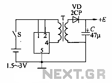
A DC booster circuit is illustrated in the figure, which represents a step-up transformer circuit diagram. The step-up transformer (T) can be utilized to power small transistor radios. The winding ratio can be adjusted to achieve the desired output...
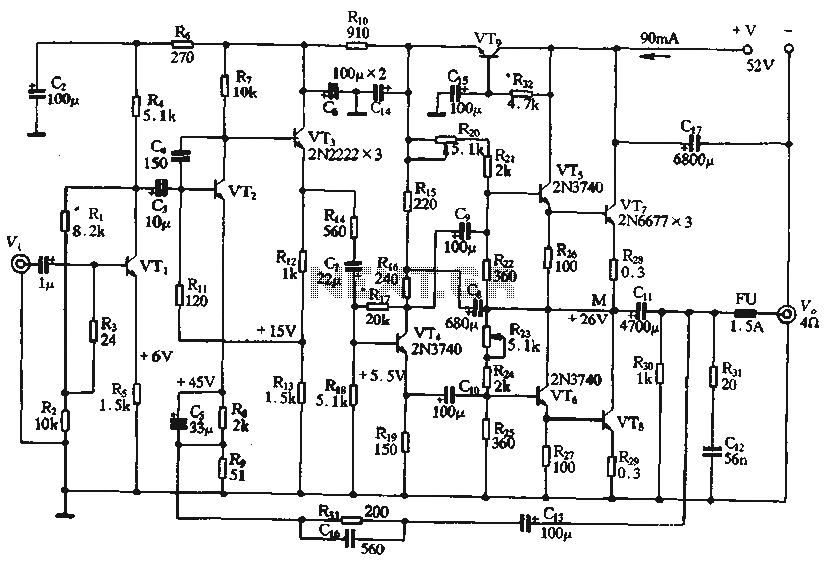
The circuit depicted in the figure is a highly technical OTL (Output Transformer-Less) amplifier circuit. It features a frequency response range of 10 Hz to 100 kHz and exhibits a total harmonic distortion of less than 0.1%, which is...
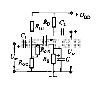
FET several basic bias circuit - self-bias voltage divider circuit The self-bias voltage divider circuit is a fundamental configuration used in Field Effect Transistor (FET) biasing. This circuit employs two resistors to create a stable bias voltage for the transistor's...
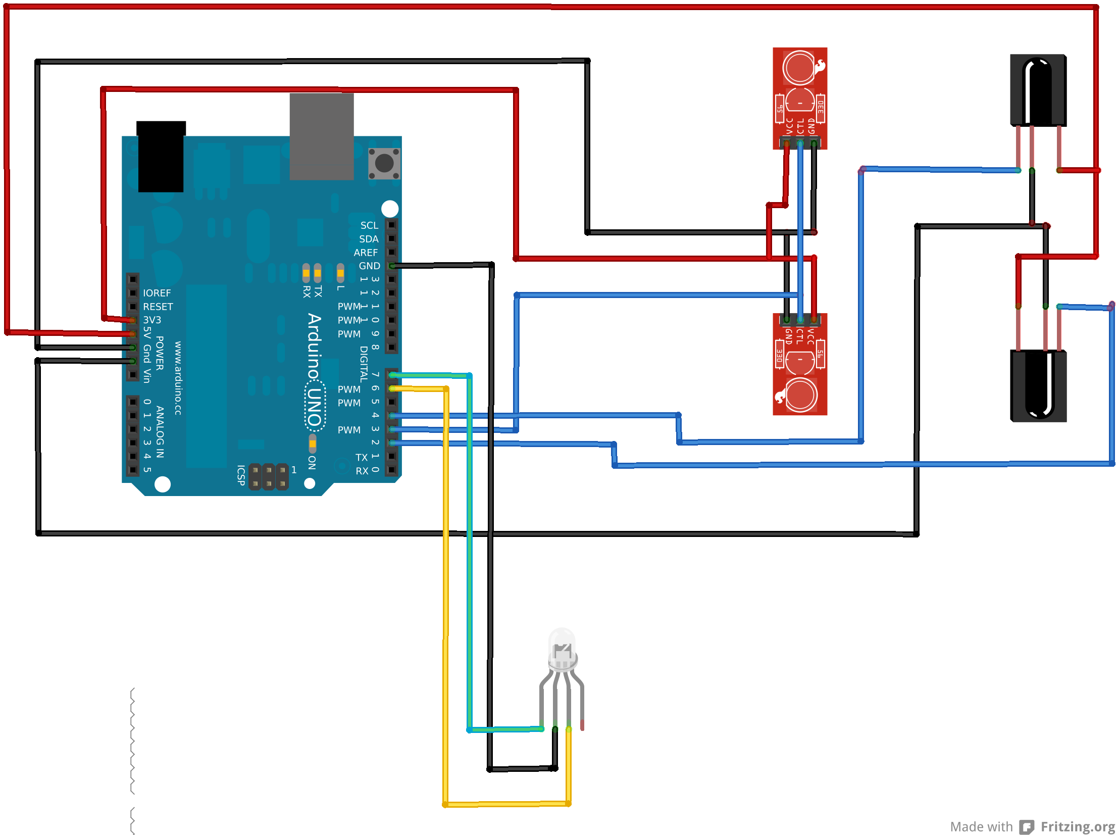
An Arduino Uno is connected to two infrared (IR) transmitters and their respective receivers. When one of the receivers detects a beam break, a strand of LEDs displays a pattern. While this setup functions correctly in principle, an issue...
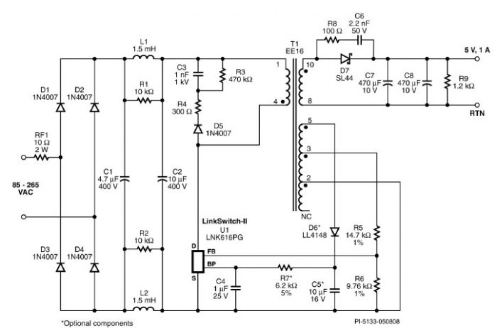
A very simple 5-volt constant voltage, constant current (CV/CC) universal-input power supply for cell phone or similar charger applications can be designed using the LNK616PG product from the LinkSwitch-II family. This low-cost charger adapter accepts a wide range of...