
Summing-amplifier-clamping-circuit
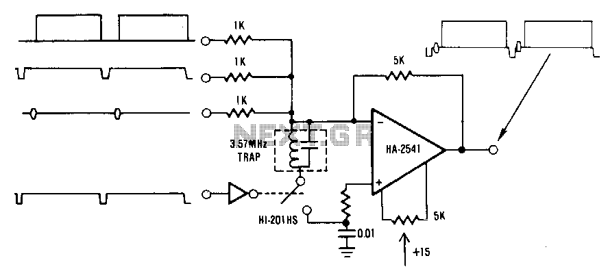
This circuit is a conventional summing amplifier configuration that incorporates a de-clamping circuit. The operation is straightforward; each component—synchronization, color burst, picture information, etc.—of the composite video signal is connected to its respective input terminal of the amplifier. These signals combine algebraically to produce the composite signal at the output. The clamping circuit, when implemented, restores the 0-V reference of the composite signal.
The summing amplifier circuit typically consists of an operational amplifier (op-amp) configured to sum multiple input signals. In this configuration, the op-amp is connected in an inverting mode, where each input signal is fed through a resistor to the inverting terminal. The non-inverting terminal is grounded, ensuring that the output signal is an inverted sum of the inputs.
The addition of the de-clamping circuit is crucial for maintaining the integrity of the composite video signal. The clamping circuit ensures that the voltage levels of the composite signal are correctly aligned to a reference level, typically 0 volts. This is particularly important in video applications, where the accurate representation of synchronization pulses and other signal components is essential for proper display.
The clamping circuit usually employs a diode and a capacitor to achieve the desired voltage reference. When the composite video signal is applied, the diode conducts during the positive half-cycles, charging the capacitor to the peak voltage level. During the negative cycles, the diode becomes reverse-biased, and the capacitor holds the voltage, effectively setting the reference level for the output signal. This process mitigates any DC offset that may be present in the input signal, ensuring a clean and stable output.
Overall, this circuit design is fundamental in video processing applications, allowing for the effective combination of multiple signal components while maintaining signal integrity through the de-clamping mechanism.This circuit is a traditional summing amplifier configuration with the addition of the de clamping circuit. The operation is quite simple; each component-synchronization, color burst, picture information, etc.of the composite video signal is applied to its own input terminal of the amplifier.
These signals combine algebraically and form the composite signal at the output. The clamping circuit, if used, restores the 0-V reference of the composite signal. 🔗 External reference