
Super lock circuit diagram
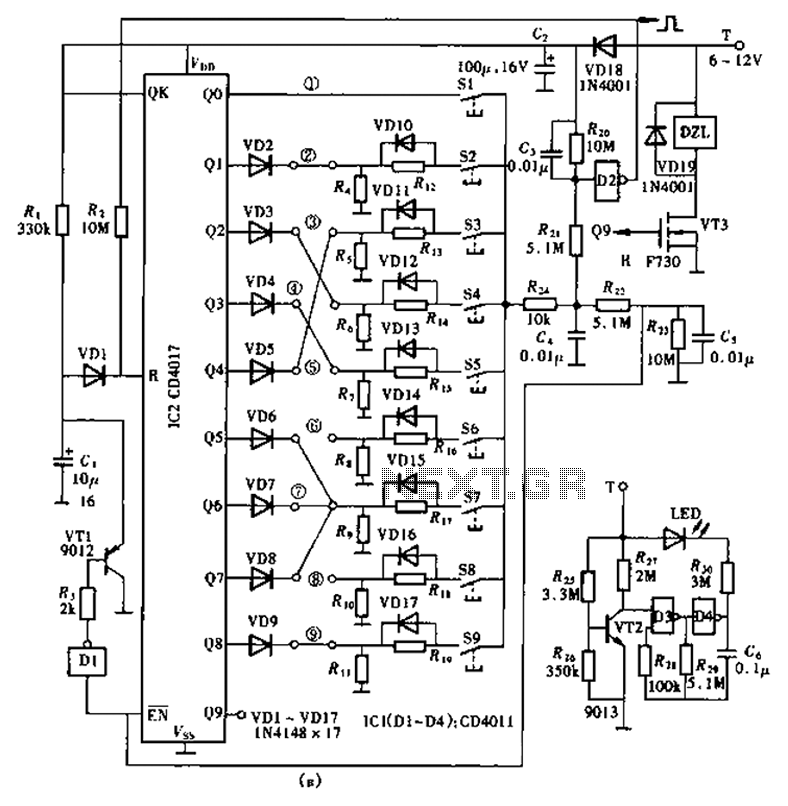
The circuit design features the CD4017 decade counter, which is capable of counting from 0 to 9, with each output terminal representing a specific count. In this application, the outputs are utilized to manage the locking mechanism based on the input of a specific password. When a valid password is entered through the input switching circuit, the corresponding output of the CD4017 is activated, allowing it to trigger a relay or another locking mechanism.
In terms of implementation, the circuit requires a power supply compatible with the operating voltage of the CD4017, typically between 3V to 15V. The password input switching circuit can be constructed using a matrix of push buttons, where each button corresponds to a digit in the password. The use of diodes in the matrix is critical to prevent ghosting and ensure that only the intended button press is registered.
The ancillary components may include resistors for pull-down configurations, capacitors for debouncing the switches, and possibly a microcontroller for additional functionality such as password management or logging attempts. The inclusion of a display, such as a 7-segment display, can provide visual feedback to the user, indicating whether the entered password is correct or incorrect.
Overall, this lock circuit design not only emphasizes security through a high number of password combinations but also maintains simplicity in its construction, making it suitable for various applications where enhanced security is required. As shown in the lock circuit by a decimal counter CD4017 composed by ten its output terminal is connected through a combination of the number of passwords the group consisting of up to 100 million group, can be called super-lock, which circuit is shown in shown. Circuit relatively simple, consisting of a CD4017 and 10 password input switching circuit related and ancillary components.
Related Circuits
This circuit is very basic to build. To open a the lock which is connected to the K1 Load you must press each momentary switch in the correct sequence. The sequence used in this circuit is S1, S2, S3,...
Power pulse circuit using LM350 and NE555. This circuit can be used to drive lamps, power LEDs, DC motors, etc. Adjust R5 for output amplitude and R1 for output power. The LM350 is an adjustable 3-terminal voltage regulator. The power...
The circuit is a battery charging system powered by Q2, Q6, R8, and D10, which provides constant current to charge the battery. When an external power supply is present, the charging current flows through R8 and D10 to charge...
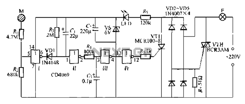
The CD4069 is a digital integrated circuit that utilizes boron to delay the activation of a light touch. It employs a j-wire connection force method and can directly replace a standard light switch without requiring changes to the existing...
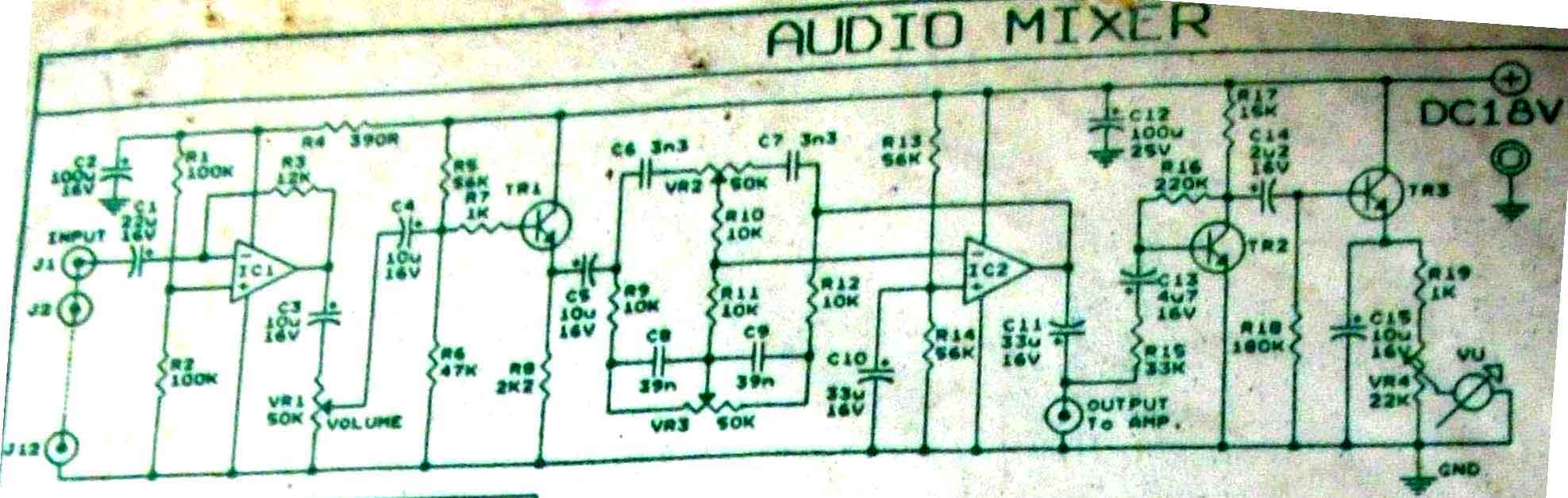
This is audio mixer circuit. The circuit is for one channel input, if you need, for example 5 channel mixer, then you need to build 5 similar circuits. The audio mixer circuit described is designed to handle a single channel...
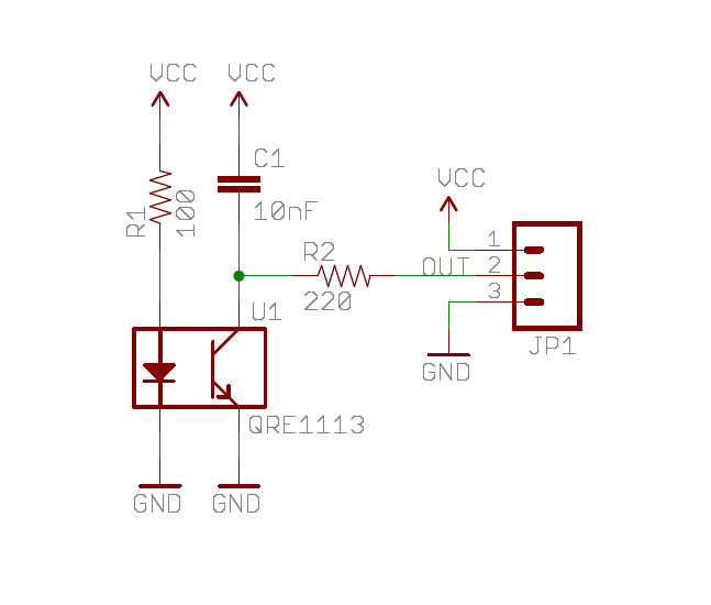
A real-time clock turns off the counter at night to conserve power. When a bee crosses under the LED, the light is reflected back to the sensor, which is a phototransistor, and triggers a digital input to the Arduino...
Warning: include(partials/cookie-banner.php): Failed to open stream: Permission denied in /var/www/html/nextgr/view-circuit.php on line 713
Warning: include(): Failed opening 'partials/cookie-banner.php' for inclusion (include_path='.:/usr/share/php') in /var/www/html/nextgr/view-circuit.php on line 713