
Super Oscillator Conversion
Take the free end of #31 or #32 AWG enameled magnet wire and insert it into the hole nearest to terminal number 3 of the coil form. Feed the wire through this hole and pull it down from inside the form. Wrap a few turns of the free end around terminal number 3 and solder the wire in place. Proceed to carefully wind a single layer of 150 turns clockwise onto the form. The term "clockwise" refers to the direction of winding as viewed from the bottom of the form. Locate a hole in the form as close as possible to the end of the winding, feed the wire through this hole, and attach it to terminal number 5, soldering it securely.
Next, using #38 AWG wire, pull out enough length to extend beyond the bottom end of the form, leaving ample wire to wrap around terminal number 2. Utilize a hot glue gun to apply a small amount of glue to the wire while holding it in place at the bottom of the mylar tape, close to terminal 1. This glue serves to secure the wire. Begin winding the primary winding onto the form in a counterclockwise direction, placing this winding on top of the mylar tape. Wind tightly for a total of 17 turns, ensuring no gaps between them. Once completed, use a piece of tape to temporarily hold the winding in place while applying additional hot glue to secure the wire.
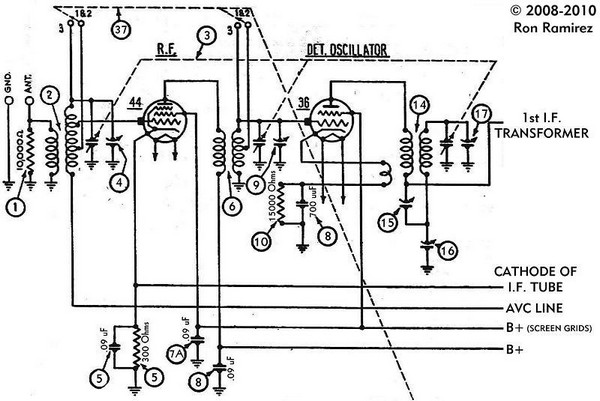
Apply a bead of hot glue from the end of the winding across the winding towards Terminal 1. Quickly lay the wire across the bead while the glue is still warm to maintain the wire's position and secure the windings. Connect terminal 5 of the new oscillator coil (14) to the "oscillator grid" (grid 1, pin 5) of the 6A7 tube, and connect the same terminal to the tuning condenser section that was previously connected to the old oscillator coil (14). Similarly, connect terminal 5 of the new oscillator coil (13) to the "oscillator grid" (grid 1, pin 5) of the 6A7 tube and to the tuning condenser section previously associated with the old oscillator coil (13).
An additional modification is necessary due to the enhanced efficiency of the 6A7 circuit compared to the 36 autodyne circuit. This increased signal strength can cause the IF amplifier circuit to oscillate. To address this, disconnect the connection between the RF amplifier tube cathode and the IF amplifier tube cathode, while keeping the 300-ohm cathode resistor and a 0.05 µF (0.09 µF in some configurations) bypass capacitor connected between the RF amplifier tube cathode and ground. Introduce a 1000-ohm resistor in parallel with a 0.05 µF capacitor between the IF amplifier tube cathode and ground. This adjustment will reduce the amplification of the IF amplifier stage to a level below the oscillation threshold.The first thing to do is to take notes indicating which wire connects where on the 36 tube socket. Remove all of the wires connected to the 36 tube socket. Then, drill out the rivets holding the five-pin 36 tube socket in place, and remove the five-pin 36 socket. You need to remove every winding from the coil, until you are left with a bare form. The inner coil form will also need to be removed. The inner form will no longer be needed, and may be set aside in your junkbox for possible future use. After you remove all of the old windings and the inner form, you should bake the form in an oven at 200 degrees for at least a half hour (an hour is even better), to dry out any residual moisture.
Taking the free end of your #31 or #32 AWG enameled magnet wire, poke it into a hole closest to terminal number 3 of the coil form. Feed the wire through the hole and pull it down from inside the form. Then wrap a few turns of the free end around terminal number 3. Now solder the wire to this terminal. Next, carefully wind a single layer of 150 turns clockwise onto the form. Clockwise indicates the direction of winding as you look at the bottom of the form. Again, find a hole in the form as close to the end of your winding as you can. Feed the wire through this hole and down through the inside of the form. Attach it to terminal number 5 and solder in place. Now, with your #38 AWG wire, feed out enough wire to stick out over the bottom end of the form, leavng plenty to wrap around terminal number 2.
With the hot glue gun, apply a small dab of hot glue to the wire while holding it in place at the bottom of the mylar tape, close to terminal 1. This glue is necessary to hold the wire in place. Now begin winding the primary winding onto the form. This is wound counterclockwise! You wind this winding on top of the mylar tape. Wind 17 turns, tightly spaced (no space between turns). Once you get 17 turns on the form, take a piece of tape and apply temporarily to hold the winding while you use some more hot glue to fasten the wire in place.
Now apply a bead of hot glue from the end of the winding, across the winding, toward Terminal 1. As soon as you lay this bead of glue down, lay the wire across the bead quickly while the glue is still hot. This will hold the wire in position as well as help hold the windings in place. Connect terminal 5 of the new oscillator coil (14) to the "oscillator grid" (grid 1, pin 5) of the 6A7 tube.
Also connect this same terminal to the tuning condenser section previously connected to the old oscillator coil (14). Connect terminal 5 of the new oscillator coil (13) to the "oscillator grid" (grid 1, pin 5) of the 6A7 tube.
Also connect this same terminal to the tuning condenser section previously connected to the old oscillator coil (13). Now, there is one more modification you will need to make. Because the 6A7 circuit is much more efficient than the 36 autodyne circuit, it will throw more signal into the IF amplifier circuit.
This extra signal strength will cause the IF circuit to go into oscillation unless something is done about it. Remove the connection between the RF amplifier tube cathode and the IF amplifier tube cathode, leaving the 300 ohm cathode resistor and.
05 uF (. 09 uF in some sets) bypass capacitor connected between the cathode of the RF amplifier tube and ground. Now add a 1000 ohm resistor, with a. 05 uF capacitor in parallel with this 1000 ohm resistor, between the IF amplifier tube cathode and ground (as shown above).
This will decrease the amplification of the IF amplifier stage to a level below the oscillation point. 🔗 External reference
Related Circuits
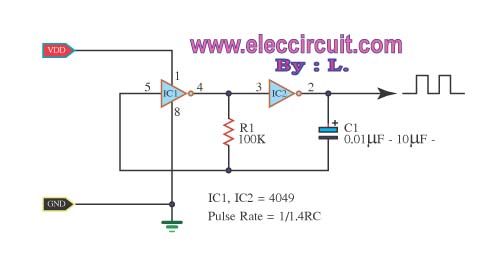
The inverter CMOS digital IC CD4049 is utilized to design a square wave oscillator generator. The CD4049 is a hex inverting buffer, which means it contains six independent inverters that can be used to generate square wave signals. This IC...
These are resonant circuits or tank circuit oscillators. They are commonly used to produce high frequencies ranging from 1 MHz to 500 MHz; hence, they are also known as RF oscillators. These oscillators are utilized in RF generators, radio...
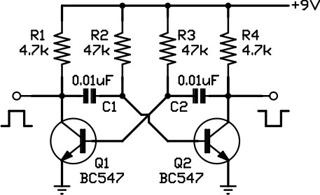
This circuit is one of the simplest to implement but can be challenging to comprehend. It consists of a two-transistor oscillator known as an astable multivibrator, which generates a square wave output that is out of phase. Initially, it...
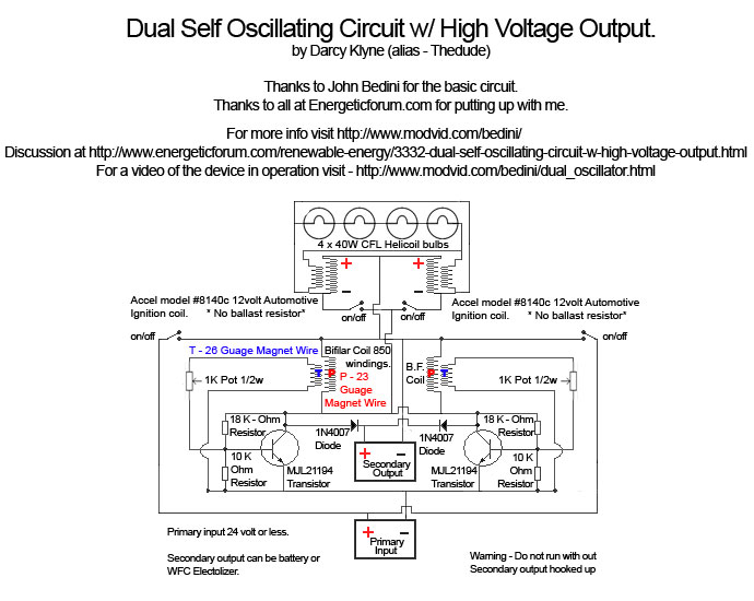
A Tesla pancake coil is connected in series with a bifilar wound coil to generate resonance and a sharp gradient discharge, which creates a vacuum flux. The circuit operates with a CFL at approximately 0.07 amps and 12.42 volts,...
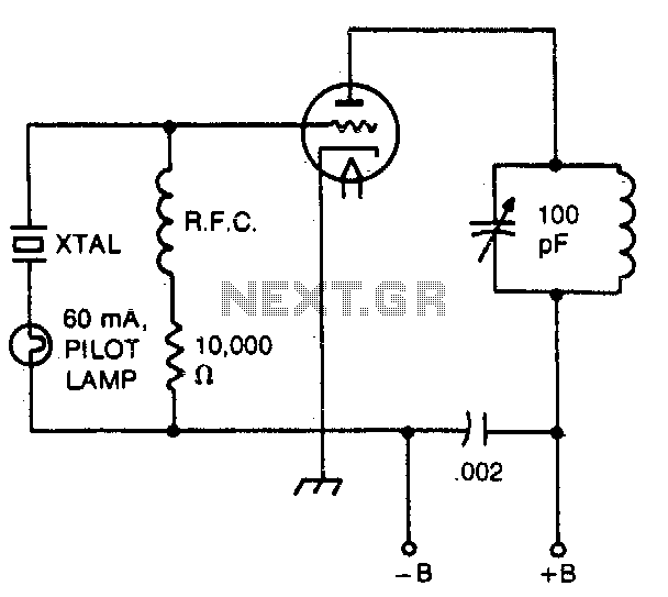
The pilot lamp limits current to prevent damage to the crystal. A very useful circuit. The circuit incorporates a pilot lamp designed to limit the current flowing to a crystal component, thereby safeguarding it from potential damage due to excessive...
This is a very simple circuit utilizing a 555 timer IC to generate a square wave of frequency that can be adjusted by a potentiometer. With values given, the frequency can be adjusted from a few Hz to several...