
SUPER SIMPLE SHORTWAVE RECEIVER
The NE602 double-balanced mixer is designed for use in various RF applications, providing effective signal processing capabilities. The circuit begins with the antenna input (J1), where RF signals are received. These signals pass through the DC-blocking capacitor (C1), which prevents any DC voltage from affecting the subsequent stages of the circuit, ensuring that only the AC signal is processed.
The RF-gain control (R1) allows for the adjustment of the signal amplitude before it is fed into the mixer. This control is crucial for optimizing the performance of the mixer, as it can help prevent saturation and distortion of the output signal. The mixer itself, U1, combines the incoming RF signal with a local oscillator signal generated internally.
The local oscillator frequency is determined by the values of the resistor (R2) and inductor (L2). Adjusting these components allows for fine-tuning of the oscillator frequency, enabling the circuit to operate across a range of frequencies as required by the application. The internal mixing process results in the generation of intermediate frequencies (IF) that can be further processed or demodulated, depending on the application.
Overall, the NE602 mixer circuit is a versatile and essential component for RF signal processing, capable of handling a variety of signal types and frequencies while providing adjustable gain and frequency settings.Integrated circuit U1 (an NE602 double-balanced mixer) is a combination oscillator and frequency mixer. Signals from the antenna input (at J1) are fed through dc-blocking capacitor C1 to the RF-gain control, R1, and fed to the input of U1 at pins 1 and 2.The local-oscillator frequency, which varies with the settings of R2 and L2, is mixed internally within U..
🔗 External reference
Related Circuits
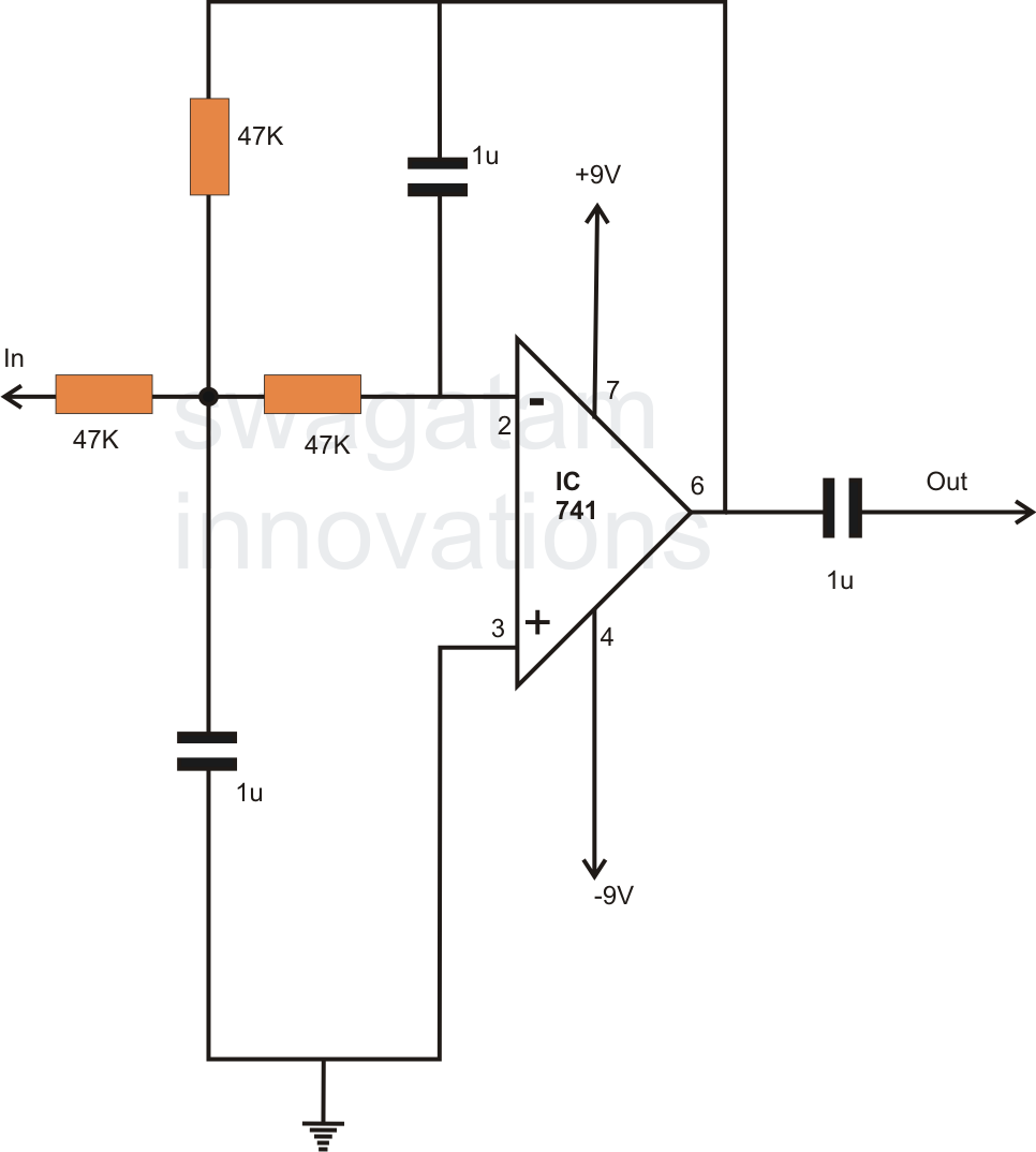
In electronics, filter circuits are primarily used to restrict the passage of certain frequency ranges while allowing other frequency bands to proceed to subsequent stages of the circuit. A high-pass filter circuit permits only frequencies that exceed a specified...
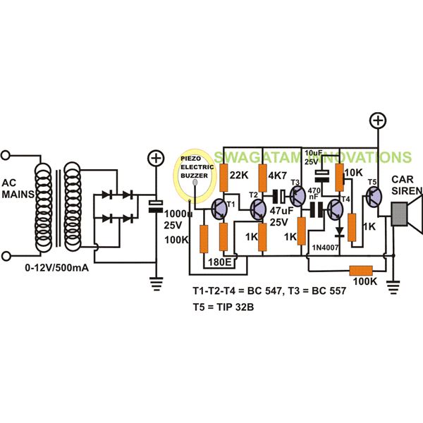
The project "DIY: Build a Sound Activated Switch" presented here is straightforward to construct and can be very useful in protecting a specific area from potential theft or intrusion. Learn how to build a simple sound-activated alarm here on...
This is a straightforward water level buzzer circuit designed to detect the water level in tanks, pools, washing machines, and similar applications. The circuit features two probes that, upon contact with water, trigger the buzzer to emit a sound....
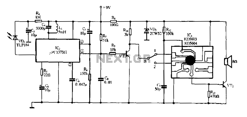
Electronic Miss Manners infrared receiver and voice circuits The Electronic Miss Manners system integrates an infrared (IR) receiver with voice circuits to facilitate communication and interaction. The IR receiver is designed to detect signals emitted from a remote control or...
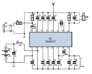
Several integrated circuits (ICs) are currently available that provide a nearly complete FM receiver solution. This project outlines a complete FM receiver circuit that offers excellent receiving and sound qualities. However, from a DIY enthusiast's perspective, the only drawback...
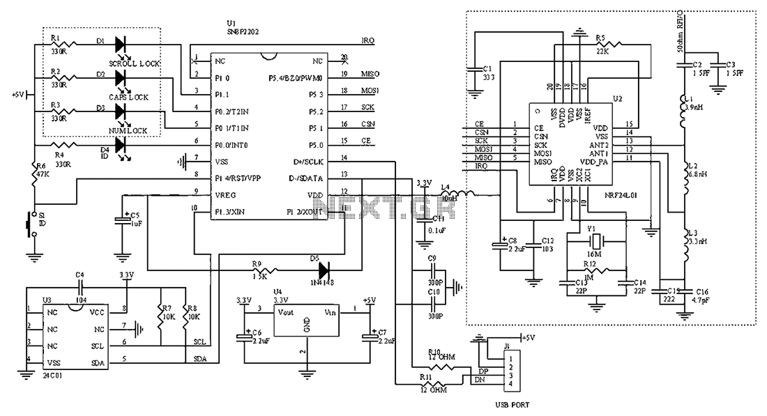
The circuit diagram for the receiving portion of a 2.4 GHz wireless keyboard is presented below. The 2.4 GHz wireless keyboard receiving circuit typically consists of several key components that work together to receive and process signals transmitted from the...
Warning: include(partials/cookie-banner.php): Failed to open stream: Permission denied in /var/www/html/nextgr/view-circuit.php on line 713
Warning: include(): Failed opening 'partials/cookie-banner.php' for inclusion (include_path='.:/usr/share/php') in /var/www/html/nextgr/view-circuit.php on line 713