
Superregenerative receiver
The RF receiver circuit described is designed for low-distance digital radio applications, operating at a frequency of 27 MHz. The primary function of this circuit is to receive radio frequency signals and convert them into a usable analog output.
The circuit includes an RF front-end that typically consists of a tuned circuit, which is formed by the inductor L1. This inductor is specified to have approximately 10 turns and a diameter of 6 mm, which is crucial for achieving the desired resonant frequency. The inductance value should be calculated based on the resonant frequency formula, considering the capacitance used in conjunction with L1 to ensure proper tuning to 27 MHz.
The output from the RF receiver is an analog signal that may contain noise and fluctuations. To improve the quality of this signal, it is recommended to connect the output to a Schmitt trigger signal conditioning circuit. This circuit will provide clean digital output by converting the analog signal into a square wave, effectively removing any noise. The Schmitt trigger utilizes hysteresis to ensure that the output transitions cleanly between high and low states, preventing false triggering due to noise.
In addition, a capacitor of an appropriate value should be placed at the collector of transistor T3, which is part of the amplification stage of the RF receiver. The capacitor will help filter the output signal, smoothing out any variations and ensuring stable operation.
Overall, this simple RF receiver design is suitable for applications requiring short-range digital radio communication, and its performance can be optimized through careful selection of component values and circuit configuration.This is a simple RF receiver mainly for low-distance digital radio receiver application. The analog output of this circuit should be connected to a schmitt-trigger signal conditioning circuit with a proper value capacitor (from collector of T3). L1 for 27Mhz is about 10 turns, 6 mm diameter coil body. 🔗 External reference
Related Circuits
Some time ago, a media center box was created to replace a DVD player, satellite receiver, VCR, and PlayStation 2 with a single device. A Core 2 Duo processor system successfully replaced all these electronic devices. However, a remote...
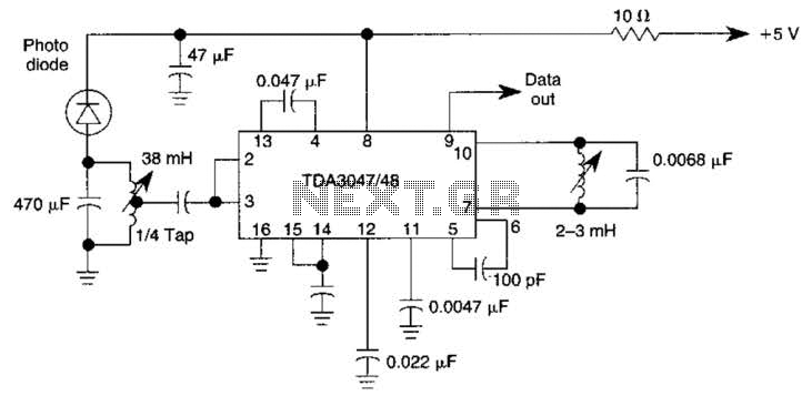
The circuit operates from a 5-V supply and has a current consumption of 2 mA. The output functions as a current source that can drive or suppress a current exceeding 75 mA with a voltage swing of 4.5 V....
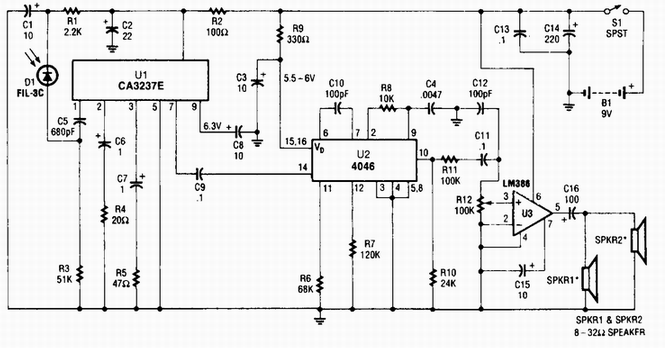
A photodiode D1 feeds a high-gain infrared (IR) remote control preamplifier IC, specifically a CA3237E. U2 is a phase-locked loop (PLL) frequency modulation (FM) detector tuned to approximately 100 kHz. The output from the detector is amplified by U3,...
This Atmel integrated circuit operates at a clock frequency of 12 MHz, facilitating communication between an infrared receiver and a personal computer. This setup enables the processing of signals by infrared receiver software, such as Girder. When a valid...
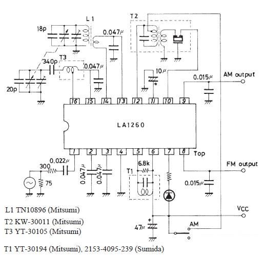
A very simple FM IF MW radio receiver circuit can be designed using the LA1260 IC manufactured by Sanyo Semiconductor. This FM IF MW radio receiver circuit schematic shows that the LA1260 IC can be utilized in AM and...
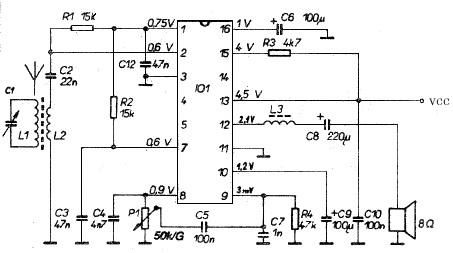
This AM radio receiver circuit utilizes the TDA1083 radio IC, which is suitable for constructing a simple medium frequency (MF) band radio. The schematic operates within a frequency range of 300 kHz to 3 MHz. The circuit is straightforward...